


9
MAINTENANCE
1. Keep all nuts, bolts, and screws tight to
keep mower in safe operating condition.
2. Never store the mower with gas in the tank
inside a building where fumes can reach an
open flame or spark. Allow engine to cool
before storing in an enclosure.
3. To reduce fire hazard, keep mower free of
grass, leaves, or excessive grease.
4. Check grass catcher assembly frequently
for wear or deterioration. Replace bag if
loose seams or tears are evident.
5. Have your mower inspected and serviced
each year by an authorized HUSQVARNA
dealer. Determine if any additional devices
are available which might upgrade the safety
of your mower.
6. Use only authentic HUSQVARNA re-
placement parts to insure the safety and
quality of your mower is maintained.
7. Safety decals should be replaced if they
are missing or illegible. Decals may be
purchased from your HUSQVARNA dealer.
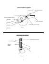
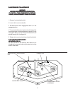
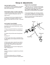
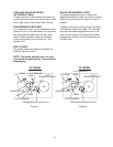
FRONT CASTER WHEELS
1. Mount front caster wheel assemblies.
Installation includes fastening casters to front
of the cutter deck using 3/8 x 1" hex head
capscrews.
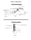
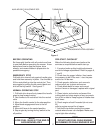
FUEL TANK
1. Place fuel tank on tank support, making sure
to get the studs through the slots on the top of
the tank support. Place the 5/16” flat washer,
spring, the other 5/16 flat washer and the 5/16”
nut on the stud. Snug 5/16” nut, but do not over
tighten.
HANDLE ASSEMBLY
1. Align the upper mounting holes in handle
with the upper hole in the tank support.
2. Install two 3/8" x 1" screws through
matched holes and loosely install 3/8" nuts.
3. Align the lower holes and install hardware
as above, tighten upper and lower hardware.
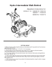
Setup & Adjustments
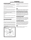
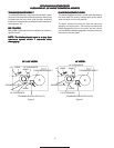
LINKAGE INSTALLATION
1. Install drive linkage into the hole in the idler
arm on the inside of the tank support. The drive
linkages are fastened to the drive levers on the
handle assembly. Secure the drive linkages to
the idler arm by inserting a retaining ring
through the small hole in the end of the drive
linkage.
2. Install shifter to transmission with 1/4" x 1"
screws.
The shifter is located in the inner box and
hardware is pre-assembled into the bracket
on the transmission.
3. Install blade control rod into the bellcrank
on the left side of the tank support. Secure
rod with ring type retainer.
4. Refer to the section of this manual on
adjustments for the proper adjustment of the
linkages you are installing. The linkages were
set at the factory but must be checked before
operating mower to insure of the proper
setting. Always check 100% of the adjust-
ments before you operate the mower.
5. Connect the two halves of the wiring har-
ness together. The four prong connectors
have a locking tab that shows which way to
line them up and guarantees that they are
connected properly when the lock snaps.
6. Install the chute deflector to the side of the
mower deck. Bolt it into place using the two
5/16" x 1" screws and nuts pre-assembled
into the mounting tabs on the deck. Tighten
the screws very securely with the chute
completely covering the discharge opening
and tight against the side of deck.
THROTTLE INSTALLATION
1. Connect the throttle cable end to the
throttle mechanism on engine, leaving the
cable clamp loose. Push throttle lever on
console completely forward. Then pull the
cable through the clamp on engine and
tighten the cable clamp. Move the throttle
lever back and forth to ensure proper installa-
tion.