


31
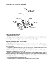
Adjustments
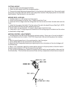
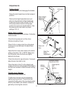
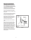
Cutting Height
Stop the mower and disengage the blades.
Raise the deck height lever to the transport
position.
Remove the height adjustment pin and
place it in the desired cutting height hole.
Lower the lift lever down onto pin. NOTE:
Anti-scalp rollers must be in the proper
position for maximum deck floatation. See
the decal on the front deck for proper
settings. FIG - 5
Lift Lever
Deck Height
Adjusment
Plates
FIG - 5
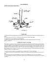
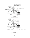
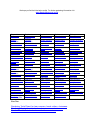
Motion
Control
Lever
Reverse Detent
Adjustment Slot
Reverse De-
tent
Spring
Deck Lift
Arm
Slots For
Chain
Adjustment
FIG - 6
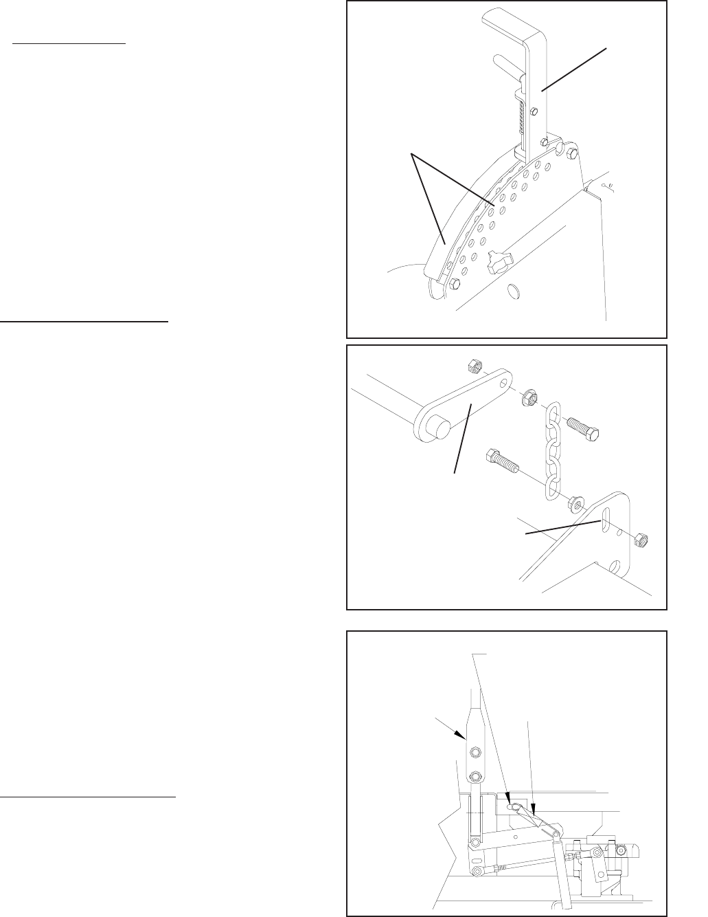
FIG - 7
Mower Deck Leveling
Position machine on a flat surface. Preferably
level concrete.
Check the tire pressure in all four tires.
Inflation should be 15 psi.
Place 2x4’s on edge under the cutting deck
from front to rear and lower the deck down
onto 2x4’s.
Adjust the four lower chain bolts to the center
slots on the deck. FIG - 6 NOTE: Make sure
the lift blocks under the frame are tightly
bolted to the frame.
Check the chains for equal tension. If unequal
adjust lower chain bolt in slot.
Place the deck in the 6” cutting height and
measure from the cutting edge of the blade to
the flat level surface to check the deck cutting
height.
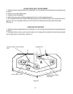
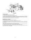
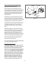
Throttle Lever Tension
Stop engine and remove key.
Throttle lever tension may be adjusted by
tightening the pivot bolt. The pivot bolt se-
cures the throttle arm to the mounting bracket
which is mounted to the console. Access is
gained by removing the console.