


33
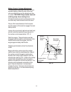
Motion Control Linkage Adjustment
This adjustment must be made with the rear
wheels rotating. Raise the rear of the ma-
chine and block it up so the wheels are free
to rotate. CAUTION: Keep hands, feet and
clothing away from rotating tires.
Tilt seat forward and remove the seat rod so
the seat may rotate forward onto the frame.
Place a 2x4 board between the foot plate
and the center of the seat to engage the seat
safety switch.
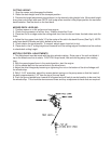
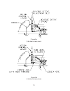
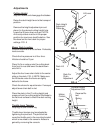
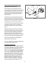
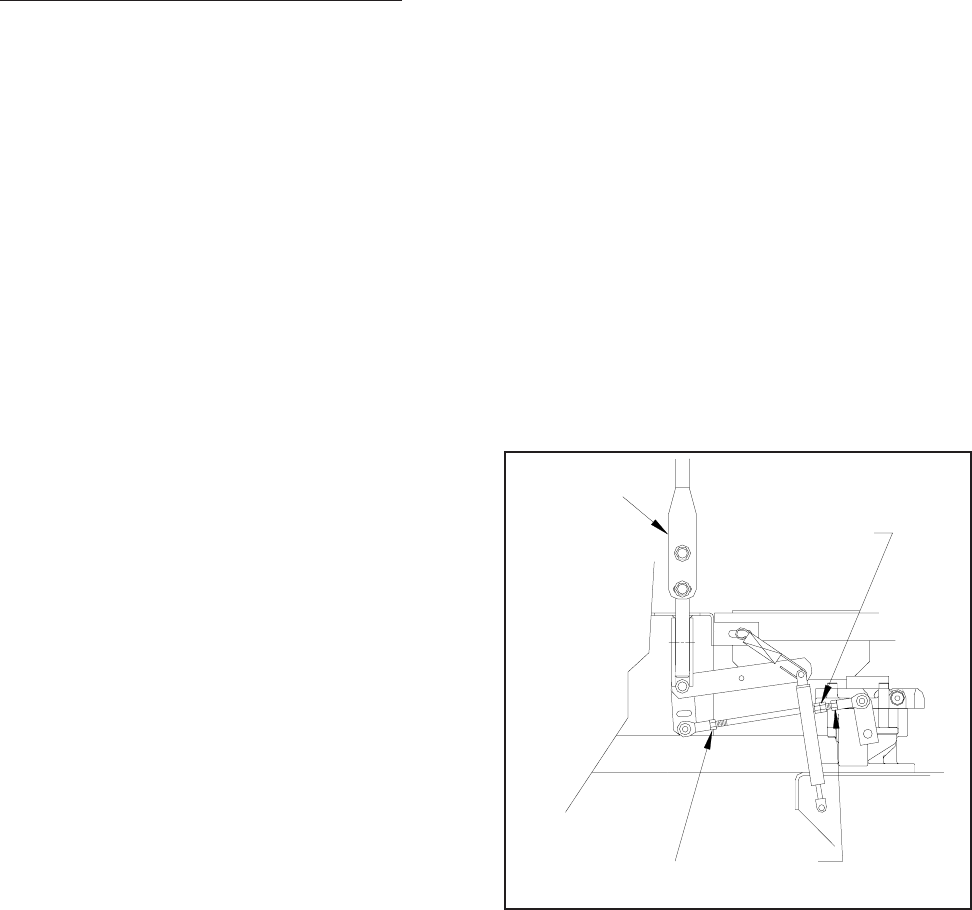
Loosen the nuts directly behind each ball joint
on both rods that connect the pump arm to
the motion control assemblies. FIG - 9
Start the engine. The park brake must be
engaged and the motion control levers in the
neutral slots to start the engine. Run the
engine approximately half throttle
Release park brake to allow the wheels to
rotate.
Begin with either side and put the motion
control lever into the neutral position. Adjust
the motion control linkage by rotating the
double nuts in the proper direction until the
wheel stops rotating. FIG - 9 Move the motion
control lever forward then into the neutral
position and place it into the neutral slot. The
wheel must be stopped completely at this
point. Now do the same in reverse and
release the lever. The lever should return to
neutral on its own. If not see reverse spring
detent adjustment.
Turn Here
To Adjust
Loosen Here
Loosen Here
(Lt. Hand
Thds.)
Motion
Control
Lever
FIG - 9