


5
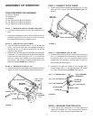
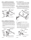
STEP 8 - TIGHTEN BOLTS
14.
At this time
tighten
the four bolts in fi gure 1 that fasten
the hitch tubes to the sweeper housing. Next,
tighten
the two bolts in fi gure 2 that fasten the ends of the hitch
tubes together. Finally,
tighten
the two bolts in fi gure 4
or 5 that fasten the hitch brackets to the hitch tubes.
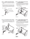
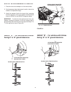
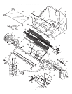
STEP 9 - ASSEMBLE THE ANGLE BRACKET
15. Assemble the angle bracket to the sweeper housing
using two 5/16" x 3/4" hex bolts and 5/16" nylock nuts.
The upright portion of the angle bracket should face
toward the left side of the sweeper. See fi gure 6.
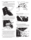
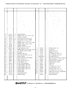
STEP 7b - ASSEMBLE HITCH BRACKETS
(For tractor hitches less than 10" above the ground.)
12.
Place the bent hitch bracket underneath the hitch tubes
and place the straight hitch bracket with hitch pin on
top of the hitch tubes. Fasten together using a 5/16" x
2-1/2" hex bolt (front), a 5/16" x 2-1/4" hex bolt (rear)
and two 5/16" hex lock nuts as shown in fi gure 5. The
bolts should straddle the front hitch tube bolt.
Do not
tighten yet.
13.
Assemble the two hitch spacers onto the hitch pin and
secure the pin with the large hairpin cotter. See fi gure 5.
5/16" x 2-1/4"
HEX BOLT
5/16" NYLOCK NUTS
HITCH PIN
BRACKET
HITCH
BRACKET
5/16" x 2-1/2"
HEX BOLT
HITCH
BRACKET
(STRAIGHT)
LARGE HAIRPIN COTTER
HITCH
SPACERS
FIGURE 5
ANGLE
BRACKET
5/16" x 3/4"
HEX BOLT
5/16" NYLOCK NUT
FIGURE 4
5/16" x 2-1/4"
HEX BOLT
5/16" NYLOCK NUTS
HITCH BRACKET
(STRAIGHT)
HITCH
BRACKET
(BENT)
HITCH PIN
BRACKET
5/16" x 2-1/2"
HEX BOLT
HITCH
SPACERS
LARGE
HAIRPIN
COTTER
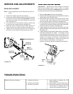
STEP 7a - ASSEMBLE HITCH BRACKETS
(For tractor hitches 10" or more above the ground.)
10.
Place the bent hitch bracket on top of the hitch tubes and
place the straight hitch bracket with hitch pin underneath
the hitch tubes. Fasten together using a 5/16" x 2-1/2"
hex bolt (front), a 5/16" x 2-1/4" hex bolt (rear) and two
5/16" nylock nuts as shown in fi gure 4. The bolts should
straddle the front hitch tube bolt.
Do not tighten yet.
11.
Assemble the two hitch spacers onto the hitch pin and
secure the pin with the large hairpin cotter. See fi gure 4.
FIGURE 6
FIGURE 7
5/16" WASHER
5/16" x 1-1/4" HEX BOLT
5/16" x 1" HEX BOLT
5/16" WASHER
5/16" NYLOCK NUT
PLASTIC GRIP
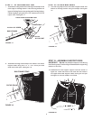
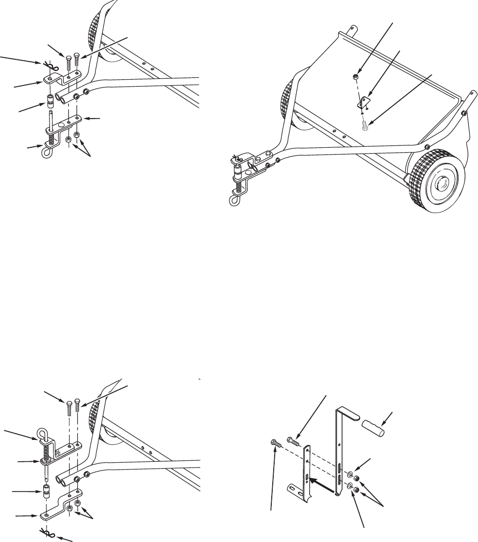
STEP 10 - ASSEMBLE HEIGHT ADJUST
HANDLE
16. Assemble the plastic grip onto the upper height adjust
handle. See fi gure 7.
17. Fasten the upper and lower height adjust handles together
as shown in fi gure 7. Use one 5/16" x 1" hex bolt, one
5/16" x 1-1/4" hex bolt, two 5/16" washers and two 5/16"
nylock nuts. Place the washers against the slots in the
upper handle. Tighten the nuts and then loosen 1/2 turn
so that the handles slide easily. See fi gure 7.