


4
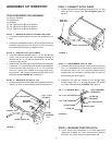
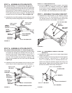
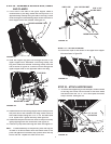
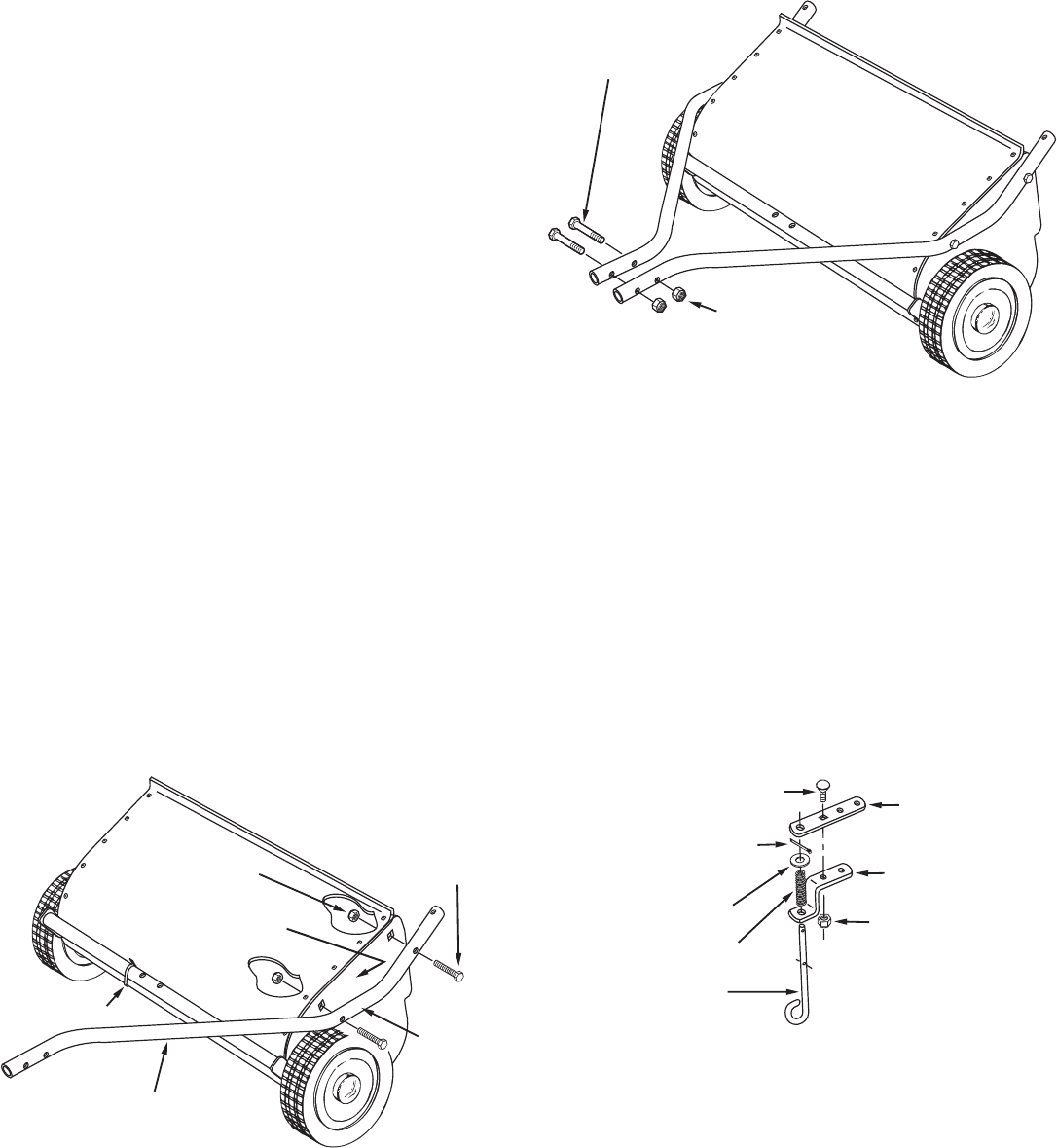
STEP 4 - CONNECT HITCH TUBES
6.
Fasten the hitch tubes together using two 5/16" x 3" hex
bolts and 5/16" nylock nuts.
Do not tighten yet.
See
fi gure 2.
FIGURE 1
FIGURE 2
FIGURE 3
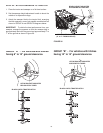
STEP 5 - ASSEMBLE HITCH PIN
7.
Assemble the hitch pin bracket , the hitch spring and then
the 7/16" fl at washer onto the hitch pin. Secure them to
the hitch pin with a 1/8" x 3/4" cotter pin placed into the
middle hole in the hitch pin. Spread ends of cotter pin
around hitch pin. See fi gure 3.
8.
Assemble the hitch pin bracket to the straight hitch
bracket using a 3/8" x 1" carriage bolt and a 3/8" nylock
nut. Align the brackets and
tighten.
See fi gure 3.
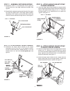
STEP 6 - MEASURE TRACTOR HITCH
9.
If your tractor hitch measures 10" or more above the
ground go to
STEP 7a
. If your tractor hitch measures
less than 10" above the ground go to
STEP 7b
.
HITCH PIN
HITCH PIN
BRACKET
HITCH SPRING
7/16" FLAT WASHER
1/8" x 3/4" COTTER PIN
MIDDLE HOLE
3/8" NYLOCK NUT
3/8" x 1" CARRIAGE BOLT
HITCH BRACKET
(STRAIGHT)
5/16" x 1-3/4"
HEX BOLT
HITCH TUBE (L.H.)
PLASTIC TIE
5/16" NYLOCK NUT
TUBE
MARKED
"77L"
HOUSING
MARKED "L"
5/16" x 3"
HEX BOLT
5/16" NYLOCK NUT
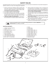
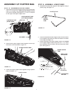
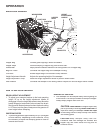
ASSEMBLY OF SWEEPER
TOOLS REQUIRED FOR ASSEMBLY
(1) Knife or Scissors
(1) Screwdriver
(1) Hammer
(1) 3/8" Open End or Box End Wrench
(2) 1/2" Open End or Box End Wrench
(1) 3/8" Open End or Box End Wrench
STEP 1 - REMOVE PARTS FROM CARTON
1.
To protect painted parts, lay them on cardboard or a
mat.
2.
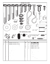
Remove the sweeper housing, the loose parts and the
hardware package from the carton. Lay out the parts
and hardware as shown on pages 3 and 4.
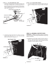
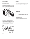
STEP 2 - INSTALL HITCH TUBES
3.
The hitch tubes are stamped with a "77
L
" for the left tube
and a "76
R
" for the right tube. The sweeper housing is
marked with an "
L
" on the left side and an "
R
" on the
right side. See fi gure 1.
4.
Hold the left hitch tube against the left side of the sweeper
so that the "77
L
" on the tube faces away from the sweeper.
Attach the hitch tube using two 5/16" x 1-3/4" hex bolts
and 5/16" nylock nuts. Repeat for the right hitch tube,
but with the "76
R
" facing in toward the right side of the
sweeper.
Do not tighten yet.
See fi gure 1.
STEP 3 - REMOVE PLASTIC TIE
5.
Remove the plastic tie that fastens the height adjustment
tube to the front of the sweeper housing. See fi gure 1.