


English – 15
ASSEMBLY
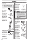
Assembling the spray guard and
trimmer head Superauto II
K
J
I
G
F
I
M
L
A
K
B
C
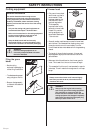
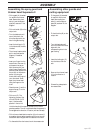
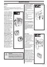
Hold the handle of the spanner as close to the trimmer
guard as possible. The nut is tightened when the spanner is
turned against the direction of rotation (left-hand thread).
• Fit the trimmer head‘s bottom section (K) on the cover (I)
by pressing the two sections together with the cut-outs on
the bottom section aligned with the catches on the cover.
• To dismantle follow the instructions in the reverse order.
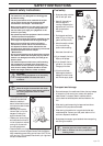
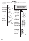
Assembling other guards and
cutting equipment
H
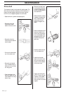
• Fit the guard (A) intended
for use with the trimmer
head. Secure using four
bolts (L) and the support
plate (M) as shown in the
diagram.
• Fit the disc drive (B) on the
output axle.
• Turn the blade axle until
one of the disc drive’s holes
aligns with the
corresponding hole in the
gear housing.
• Insert the locking pin (C)
into the hole to lock the
axle.
• Screw on the trimmer head
(H) in the direction of
rotation.
• Dismantling takes place in
the reverse order.
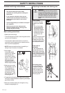
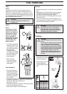
• Fit the guard (A) intended
for use with the trimmer
head. Secure using the 4
bolts (L) and the support
plate (M) as set out in the
diagram.
• Fit the drive disc (B) on the
output axle.
• Turn the blade axle until
one of the holes in the
drive disc aligns with the
hole in the gear housing.
• Insert the locking pin (C)
in the hole so that the axle
is locked.
• The trimmer head must be
split to be fitted (see the
diagram). Proceed as
follows:
• Insert your finger into the
centre hole of the cover (I)
at the same time as you
hold the cover with your
other fingers. Press the two
catches (J) that extend from
the cut-out on the bottom
section (K) using the
thumb and index finger of
your other hand. Press
apart the trimmer head
using the fingers on the
cover.
• Place the cover (I) and the
support flange (F) on the
output axle.
• Fit the nut (G). The
tightening torque of the
nut is 35-50 Nm (3,5-5
kpm). Use the socket
spanner in the tool kit.