Service and Troubleshooting
0144 5-7
3. Hook spring (25) over post so that hook lies flat against rear of housing.
4. Make sure lower arm and overthrow stop pawl (19) fits into slot in reset lever.
5. To time the register for zero reset, pry apart the center wheel and (13 and 16) and place 16
on middle post with two red marks pointing toward the other two posts. Line up the red
arrows on the lefthand and righthand wheels with marks on the center wheel as shown in
drawing. Make sure pawls 15 and 17 remain in grooves of lefthand and center (16) reset
gears (lefthand pawl-red, center pawl-white). Seat count gear (13) over hub of and down
against reset gear (16). Listen to it snap into place.
6. Install righthand overthrow stop (19) on post with lower arm engaged in rectangular cutout in
reset lever (24). Install center and lefthand overthrow stop (11) on post so that upper arm of
19 fits in the recess in 11 and both stops are driven simultaneously by reset lever (24) during
reset.
7. If detent spring (21) and retainer (20) become separated, reassemble on post so that short
leg of spring points toward top of register.
8. If all parts are removed from the register, reassemble in the reverse order in the following
sequence: 27-35, 36, 41, 37, 40, 39, 38, 2, 3, 1, 26, 24, 25, 23, 22, 19, 16, 17, 14, 15, 12, 18,
13, 11, 21, 20, 10, 9, 8, 32, 31, 30, 29, 28.
9. Test register for zero reset (one short downward stroke of the reset lever resets register to
zero) and turn control block (39) by hand to record at least one gallon on the register. Make
sure O-ring seal on the rear of the housing is clean and the O-ring (34) is free of nicks or cuts
and will lay flat within the seat. Reassemble the meter to the register.
4860 4-WHEEL REGISTER SERVICE
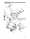
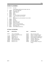
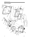
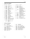
NOTE: Numbers in parentheses correspond to the numbers shown on the parts illustration
and parts list in Section 6 labeled
4860 4-Wheel Register
.
To service push button register, remove two (one on each side) screws (2) from bezel (1).
Remove bezel and dial mask (4). Reset button (5) and spring (6) are released when the dial
mask is removed. Remove screws (7), reset bearing (8) and screws (11) to lift register assembly
(10) out. Drive shaft assembly (12) can be removed by taking out four bearing screws.
Replacing Bearing and Seal Assembly (Item 16, Old Style)
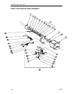
To replace the shaft seal or service the gear train on back of register housing (18), remove
housing from meter body by taking out four screws.
NOTE: The meter housing will be full of liquid
so some means should be available to catch what drains from the case and lines.
To remove
gears (22-25), remove three retaining rings (20) and drive key (21). Withdraw the drive shaft and
gear (14), spacer (15), meter stuffing box (16), and O-ring (17). Slide new O-ring over new
bearing seal like you would slide a ring on your finger. Insert shaft (14) through spacer (15) and
bearing (16) as shown in the exploded view. Press entire assembled shaft and seal through
housing and seat the square of the bearing firmly into the recess in the register housing (18).
Reassemble the balance of the register in reverse order of disassembly.


