


GASBOY Series 70 & 1820
5-6 0144
1860 3-WHEEL REGISTER SERVICE AND MAINTENANCE
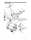
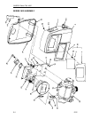
NOTE: Numbers in parentheses correspond to the numbers shown on the parts illustration
and parts list in Section 6 labeled
1860 3-Wheel Meter-Register
.
To service or replace parts in the disc register, remove the self-tapping screws and lift off the front
panel assembly. With the register now exposed, remove three screws with fiber washers (28 &
29). Lift off dial glass (30), and dial mask (32). This permits withdrawal of all parts (8 through 22).
While removing parts, observe the position and relationship of the parts to each other to assist
reassembly.
Totalizer assembly (3) can be taken out by removing screw (1). Replace as an assembly.
To gain access to the gear train (39, 40, 41 or 44 through 49), the register (1 through 33) can be
removed as an assembly by taking out 4 screws and lifting it off the meter body. This is a liquid-
carrying section of the meter. Be prepared to catch any liquid drained from the system at this
point.
The cluster gear (40), controls the gear ratio change for gasoline or diesel fuel in U.S. or Imperial
measure and is removed by taking off the retaining ring (38) and control block (39). For liter
measure, the drive gear (41) controls this ratio, and the drive key (37) must be removed to replace
this gear.
For full liter models, the cluster gear (45) controls the gasoline-diesel ratio change. To replace
this gear, both the retaining ring (38) and drive key (37) must be removed, and gears (44, 49, 47,
and 48) removed in that order.
Replacing Bearing and Seal Assembly (Item 36, Old Style)
To replace bearing and seal assembly (36), remove all gears in gear train (39, 40, 41) or (44, 47,
48, and 49). Do not lose spacer washer (43). Disassemble items 8-19 and 28-32 from register.
Withdraw gear and shaft (27), bearing and seal assembly (36) and O-ring (35). Slide new O-ring
(35) over bearing and seal (36) like a ring on a finger. Insert gear and shaft (27) through housing
(33) from front to rear and through O-ring seal assembly (35 and 36). Press seal and shaft
together to seat bearing and seal firmly into square cavity in back of housing. Reassemble in
reverse order.
Replacing Bearing and Seal Assembly (Item 36, New Style)
To replace bearing and seal assembly (52), remove all gears in gear train (39, 40, 41) or (44, 47,
48 & 49). Do not lose spacer washer (43). Disassemble items 28-32 and 8-19 from register.
Withdraw gear and shaft (27). Remove the nylon washer which is part of item 52 and note its
location. Remove both oilite bearings and both O-rings from bore in register housing. Using new
parts, which consist of a new nylon washer, 2 oilite bearings, and 2 O-rings, reassemble parts in
reverse order. Be sure to lubricate both O-rings with an O-ring lubricant before assembling.
When assembling the disc register, observe the following precautions.
1. For full liter models, make sure the spacer washer (43) lies between the control block and
gear (44) and the rear of the housing (33) on the control block post. The function of the
remaining plate is to stabilize the shaft (27) and ensure full engagement of gears in the drive
train (44-49).
Reassemble the full liter train in the order 46, 45, 48, 47, 49, and 44. The gears drive in their
number sequence (i.e. 44 drives 45, 45 drives 46, etc.)
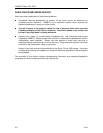
2. A new drive key (37) is L-shaped as shown in drawing. After insertion through hole in shaft
(27) and slot in gear (41 or 49) hub, the long leg of L must be bent up to form a U shape and
capture the key and drive the gear train.