


12
42858-01 • 09/10/09 • Hunter Fan Company
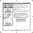
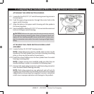
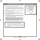
ATTACHING THE UPPER SWITCH HOUSING
8-5. Locate the four #6-32 X 1/4" switch housing mounting screws in
the sack parts.
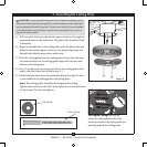
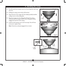
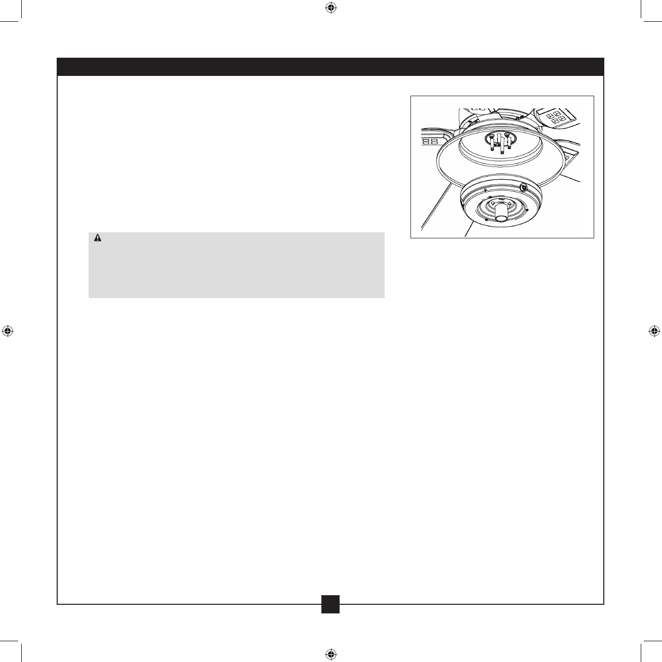
8-6. Feed the upper plug connector through the center hole in the
upper switch housing.
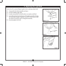
8-7. Align the holes in the upper switch housing with the spokes in
the mounting plate.
8-8. Insert and tighten the four #6-32 X 1/4" screws into the outermost
holes in the upper switch housing.
CAUTION: Make sure the upper switch housing is securely attached
to the switch housing mounting plate. Failure to properly attach and
tighten all four housing assembly screws could result in water entry
into live connection area and/or the switch housing and light xture
falling.
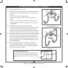
ATTACHING THE LOWER SWITCH HOUSING/LIGHT
ASSEMBLY
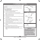
8-9. Locate the four #6-32 X 3/8" housing screws.
NOTE: Depending upon your fan model, these screws may be
installed in the four spokes from the switch housing mounting
plate, or they may be located in the sack parts.
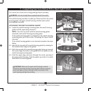
8-10. Install the screws halfway into the four spokes from the switch
housing mounting plate.
NOTE: If these screws came installed, make sure that they are
installed halfway in order to complete the following steps.
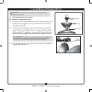
8-11. Connect the upper plug connector to the lower plug connector
from the lower switch housing assembly.
NOTE: Both plug connectors are polarized and will only t
together one way. Make sure that both connectors are properly
aligned before connecting them together. Incorrect connection
could cause improper operation and damage to the product.
8 • Completing Your Installation With a Bowl Light Fixture (continued)
Step 8-6