


11
42858-01 • 09/10/09 • Hunter Fan Company
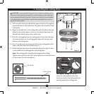
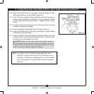
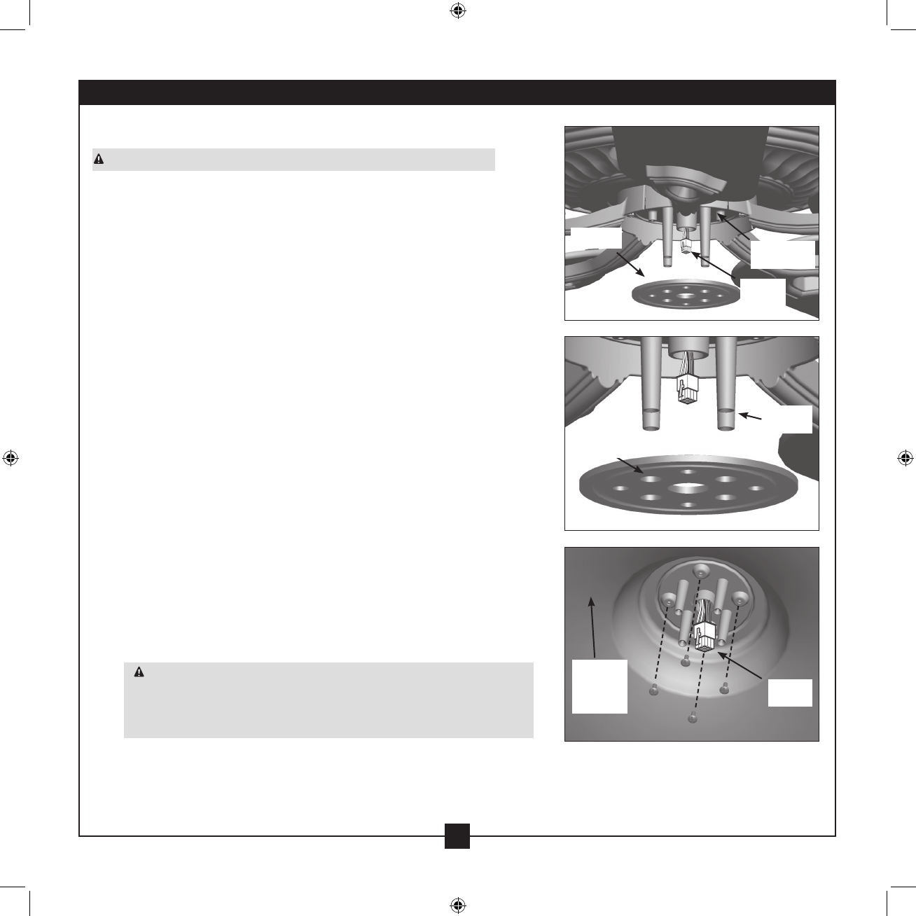
Gasket
Holes
Mounting
Plate
Spokes
Upper
Plug
Upper
Plug
Upper
Switch
Housing
11
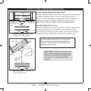
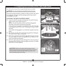
8 • Completing Your Installation With a Bowl Light Fixture
Your Hunter fan comes with an integrated light xture assembly.
WARNING: Use only the light xture supplied with this fan model.
e switch housing assembly is made up of three sections: the switch
housing gasket, the upper switch housing, and the lower switch
housing/light assembly.
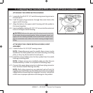
ATTACHING THE SWITCH HOUSING GASKET
8-1. Locate the switch housing mounting plate, the switch housing
gasket and the upper plug connector.
NOTE: Your fan may come with the switch housing gasket
attached to the switch housing mounting plate.
If the switch housing gasket is attached to the switch housing
mounting plate, go to the section "Attaching the Upper Switch
Housing."
If the switch housing gasket is not attached complete the steps
below.
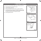
8-2. Identify the top side of the switch housing gasket by looking for
the raised circular ridge on the gasket.
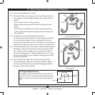
8-3. With the top side of the switch housing gasket facing up towards
the motor, align the holes in the gasket with the spokes on the
switch housing mounting plate.
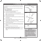
8-4. Feed the upper plug connector through the center opening of
the upper switch housing. Push the gasket up so that it is seated
ush with the mounting plate.
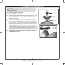
CAUTION: Make sure the upper switch housing is securely
attached to the switch housing mounting plate. Failure to properly
attach and tighten all three assembly screws could result in the
switch housing and light xture falling.
Step 8-1
Step 8-2
Step 8-4