


PRIMUS
R
660 Digital Weather Radar System
A28–1146–111
REV 2
Normal Operation
4-2
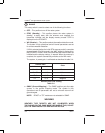
Step Procedure
5 When power is first applied, the radar is in WAIT for
approximately 90 seconds to allow the magnetron to warm
up. Power interruptions lasting less than 3 seconds result
in a 6–second wait period.
NOTE: If forced standby is incorporated, it is necessary to exit forced
standby.
WARNING
OUTPUT POWER IS RADIATED IN TEST MODE.
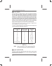
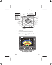
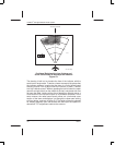
6 After the warm–up, select the test mode and verify that the
test pattern is displayed, as shown in figure 4–2. If the
radar is being used with an EFIS, the test pattern is similar.
The antenna position indicator (API) is shown as a yellow
arc at the top of the display.
NOTE: The API (a strap option) paints and unpaints on alternate sweeps to
supply a continuous indication of picture bus activity. The color of the
text does not change on alternate sweeps.
7 Verify that the azimuth marks, target alert (TGT), and
sector scan controls are operational.
PRIMUS
R
660 Power–Up Procedure
Table 4–1