


5
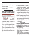
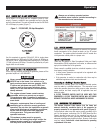
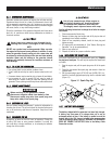
Figure 1C Wheel Assembly
The unit has been deliberately shipped with the battery cables
disconnected. You will need a 10mm wrench to secure the battery
cables.
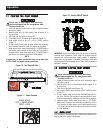
To connect the battery (see Figure 15 for connection details):
1. Cut off cable ties securing battery cables.
2. First, connect the red cable to the positive (+) battery terminal
with the supplied bolt.
3. Connect the black cable to the negative (-) battery terminal
with the supplied bolt.
4. Make sure all connections are secure. Slide the rubber boots
over the terminals and connection hardware.
NOTE:
If the battery is unable to start the engine, charge it with the
12V charger included in the accessory box (see the "Charging a
Battery" section for details).
Read the Owner’s Manual and Safety Rules before operating
this generator.
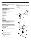
Compare the generator to Figures 2 through 4 to become
familiarized with the locations of various controls and adjustments.
Save this manual for future reference.
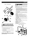
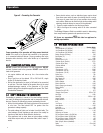
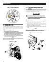
1. 120 Volt AC, 20 Amp, Duplex Receptacle – Supplies electrical
power for the operation of 120 Volt AC, 20 Amp, single-phase,
60 Hz electrical lighting, appliance, tool and motor loads.
2. 120/240 Volt AC, 30 Amp Locking Receptacle – Supplies
electrical power for the operation of 120 and/or 240 Volt AC,
30 Amp, single-phase, 60 Hz, electrical lighting, appliance,
tool and motor loads.
3. Circuit Breakers (AC) – Each receptacle is provided with
a circuit breaker to protect the generator against electrical
overload.
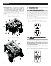
4. Oil Drain – Use to drain engine oil.
5. Air Filter – Filters intake air as it is drawn into the engine.
6. Choke Knob – Used when starting a cold engine.
7. Fuel Tank – See generator Specifications for tank capacity.
8. Grounding Lug – Ground the generator to an approved earth
ground here. See "Grounding the Generator" for details.
9. Run/Stop Switch – Controls the operation of the generator
(pull start models).
9A. Start Switch – Used to start engine from the starter motor
(electric start models only).
10. Muffler – Quiets the engine.
11. Handles – Pivot and retract for storage. Press the spring-
loaded button to move handles.
12. Gas Cap – Fuel fill location.
13. Fuel Gauge – Shows fuel level in tank.
14. Oil Fill – Add oil here.
15. Recoil Starter – Use to start engine manually.
16. Fuel Shut Off – Valve between fuel tank and carburetor.
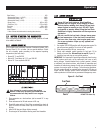
Figure 2 - Control Panel
Operation