


Installation Instructions
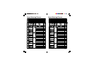
Power Supply Connections
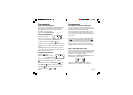
The controller itself can run off a 240V AC to 24V AC
external transformer..
It is recommended that the transformer is not connected
to a 240V AC supply which is also servicing or supplying
motors (i.e. Air conditioners, pool pumps, refrigerators,
etc.) Lighting circuits are suitable as a power source.
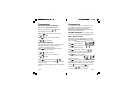
Connections to the unit are as follows:
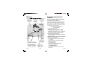
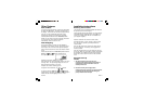
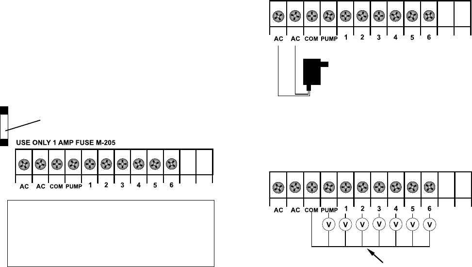
Connection Of Valves
Up to two 24VAC Solenoid Valves can be connected to
each station output and wired back to the common (COM)
thus:
Valve wires enter the controller
through the rear
Field Wiring Connections
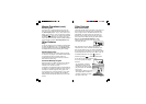
PREPARATION
1 Prepare wires for hook-up by cutting the wires to the
correct length and stripping approximately 6.0mm
(¼ inch) of insulation from the end to be connected to
the controller.
2 Ensure terminal block screws are loosened
sufficiently to permit easy access for wire ends. Insert
stripped wire ends into the clamp aperture and
tighten screws. Do not over tighten as this may
damage the terminal block.
3 A maximum of 0.5 Amps may be supplied by any
output. Check the inrush current of your solenoid coils
before connecting more than two valves to any one
station.
Installation Instructions
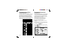
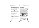
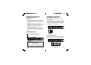
Terminal Block Layout
The terminal block is laid out as follows:
GLOSSARY
AC 24VAC Power Supply
COM Common valve wire input
PUMP Master valve or pump start active wire
ST1 to ST6 Station (Valve) active wire connection
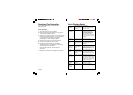
PAGE 19PAGE 18
Fuse located under battery cover.