


6
English
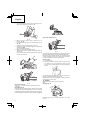
5. Guide the chain drive links into the bar groove all around the bar.
6. Install the side case (3) onto the bolts (6).
Make sure that the boss of chain tension adjust bolt (8) fi ts into the
hole of the bar (9). (Fig. 4)
Then tighten the guide bar clamp nut (2) by hand that allows the
chain bar end to move up and down easily. (Fig. 2)
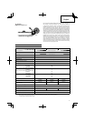
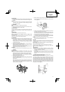
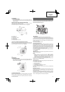
7. Raise the bar end, and tighten the saw chain (10) by turning the
tension adjustment bolt (11) clockwise. To check proper tension,
lightly lift up the center of chain and there should be about 0.5 – 1.0
mm clearance between bar and edge of drive link (12). (Fig. 6, 7)
12
11
10
0.5-1.0 mm
Fig. 6
Fig. 7
CAUTION
PROPER TENSION IS EXTREMELY IMPORTANT
8. Raise the bar end and securely tighten the guide bar clamp nut
with the combi box spanner. (Fig. 7)
9. A new chain will stretch so adjust the chain after a few cuts and
watch chain tension carefully for the fi rst half hour of cutting.
NOTE
Check the chain tension frequently for optimum performance and
durability.
CAUTION
○ When the chain is excessively tightened, the bar and chain will
be damaged rapidly. Conversely, when the chain is excessively
loosened, it may get out of the groove in the bar.
○ Always wear gloves when touching the chain.
WARNING
During operation, hold chain saw fi rmly with both hands. A single
hand operation may cause serious injury.
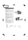
ASSEMBLY PROCEDURES
WARNING
Never try to start engine without side case, bar and chain securely
fastened.
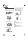
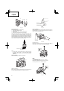
1. Pull the chain brake (18) toward the front handle to check that the
brake is disengaged. (Fig. 15)
2. Remove guide bar clamp nut (2). Remove the side case (3) (Fig. 2)
3
2
Fig. 2
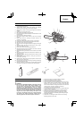
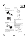
* In case of installing the spiked bumper (4), install the spiked
bumper (4) to the unit with two screws. (Fig. 3)
4
Fig. 3
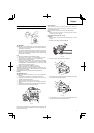
3. Install the guide bar (5) onto the bolts (6), then push it toward the
sprocket (7) as far as it will go. (Fig. 4)
7
5
6
9
8
Fig. 4
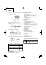
4. Confi rm the direction of saw chain (10) is correct as in the fi gure,
and align the chain on the sprocket. (Fig. 5)
10
Fig. 5