


5. External Wiring
5-1
5. External Wiring
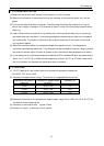
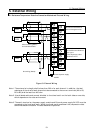
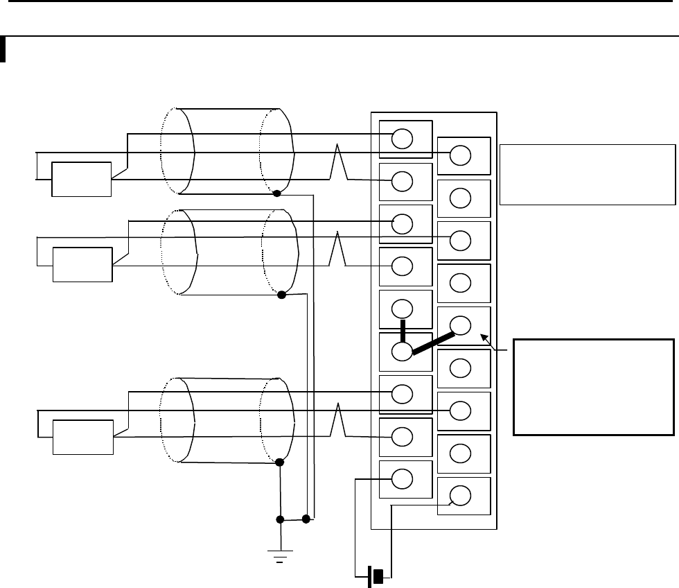
5.1 Resistance Temperature Detective Connection Method and External Wiring
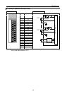
Figure 5.1 External Wiring
Note 1: The external wire length shall be less than 200 m for each channel. In addition, the total
resistance of the wires of each channels to be connected to the current terminals (A0 to A3,
B0 to B3) shall be less than 400 ohm.
Note 2: Use shielded cable and connect shielded to functional earth on the both sides or one side,
which depends on the noise environment.
Note 3: The earth terminal on the power supply module and External power supply 24 VDC must be
connected to the functional earth. When functional earth area doesn't do, temperature data
sometimes become unstable. The data becomes unspecified.
b0
B0
b1
B1
b2
B2
b3
B3
+24V
A0
NC
A1
NC
A2
NC
A3
NC
-24V
External power supply
24VDC
Grounding (Note2)
External wiring(Note1)
Use a shielded cable
Make a short-circuit on
unused channel shown as
the figure.
The temperature data
becomes H7FFF.
A0 to 3 : Current terminal
B0 to 3: Current terminal
b0 to 3: Voltage terminal
RTD
RTD
RTD