2. Structure and Nameplate
2-1
2. Structure and Nameplate
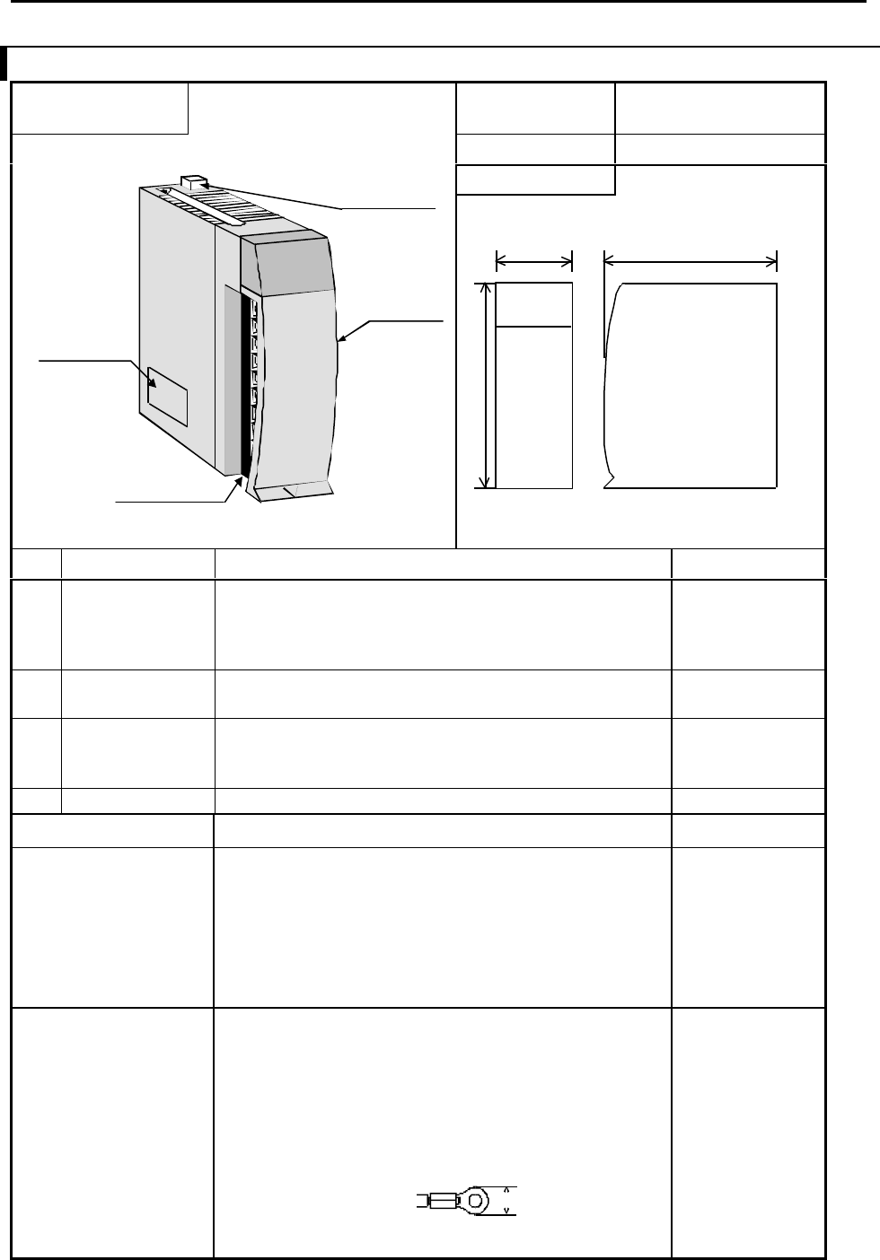
2.1 Structure and Name of Each Part
Name and function of
each part
Type EH-PT4
Weight
Approx. 180 g
Dimensions(mm)
No.
Name
Function Remarks
1) Lock button This is used when removing the module from the
base unit. After it is installed to the base unit, the
fixation can be reinforced using screws. In this
case, use M4x10mm screws.
2) I/O cover This is the cover attached to the terminal block
area.
3) Terminal block
This is the terminal block for connecting input
signals. The terminal block can be connected or
disconnected.
4) Setting Switch This is used for setting of temperature range. Refer chapter 6.
Item Detailed explanation Remarks
Operation explanation
The module receives input signals from outside.
While the module energized,
The CPU module recognizes the status of the loaded
module and when it matches the I/O assignment
information included in the user program. Input
information is received according to the contents of
the user program.
Terminal block The screws for the terminal block are M3 screws.
Use a crimp terminal that fits the screw diameter.
The maximum thickness of the cable should be only
up to 0.75 SQ.
The recommended crimp terminal is indicated
below.
4)
Setting Switch
3) Terminal Block
30 95
100


