


4. Block Diagram
4-1
4. Block Diagram
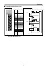
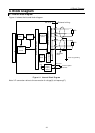
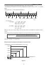
4.1 Internal Block Diagram
Figure 4.1 shows the internal block diagram.
Figure 4.1 Internal Block Diagram
Note: V/F conversion refers to the conversion of voltage(V) to frequency(F).
RTD
External grounding
B0
b0
A3
B3
b3
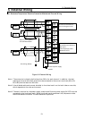
External wiring
CPU Bus
24 V DC−
External power
24V DC
24 V DC+
EH-PT4
V/F
conversion
(Note)
Counter
Timing
control
Input conversion circuit
Constant
current
circuit
Each
part
Switch circuit
Internal
Power
Supply
circuit
A0
Line-
arize
Shielded
wire
Photocoupler insulation
RTD