


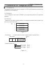

3.Specification
3-2
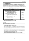
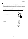
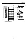
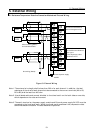
3.2 Terminal layout and internal circuit
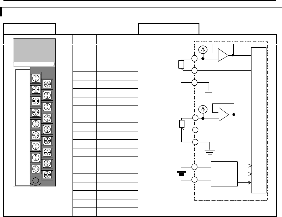
Terminal layout Internal circuit
No. Signal name
1) b0
2) B0
3) b1
4) B1
5) b2
6) B2
7) b3
8) B3
9) 24V DC+
10) A0
11) NC
12) A1
13) NC
14) A2
15) NC
16) A3
17) NC
18) 24V DC-
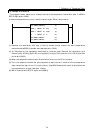
Note 1) Current terminals and a voltage terminals of unused channels should be wired. By this
wiring read data becomes H7FFF.
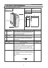
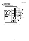
PT100 IN EH-PT4
RTD
RTD
Internal
power
circuit
Internal current