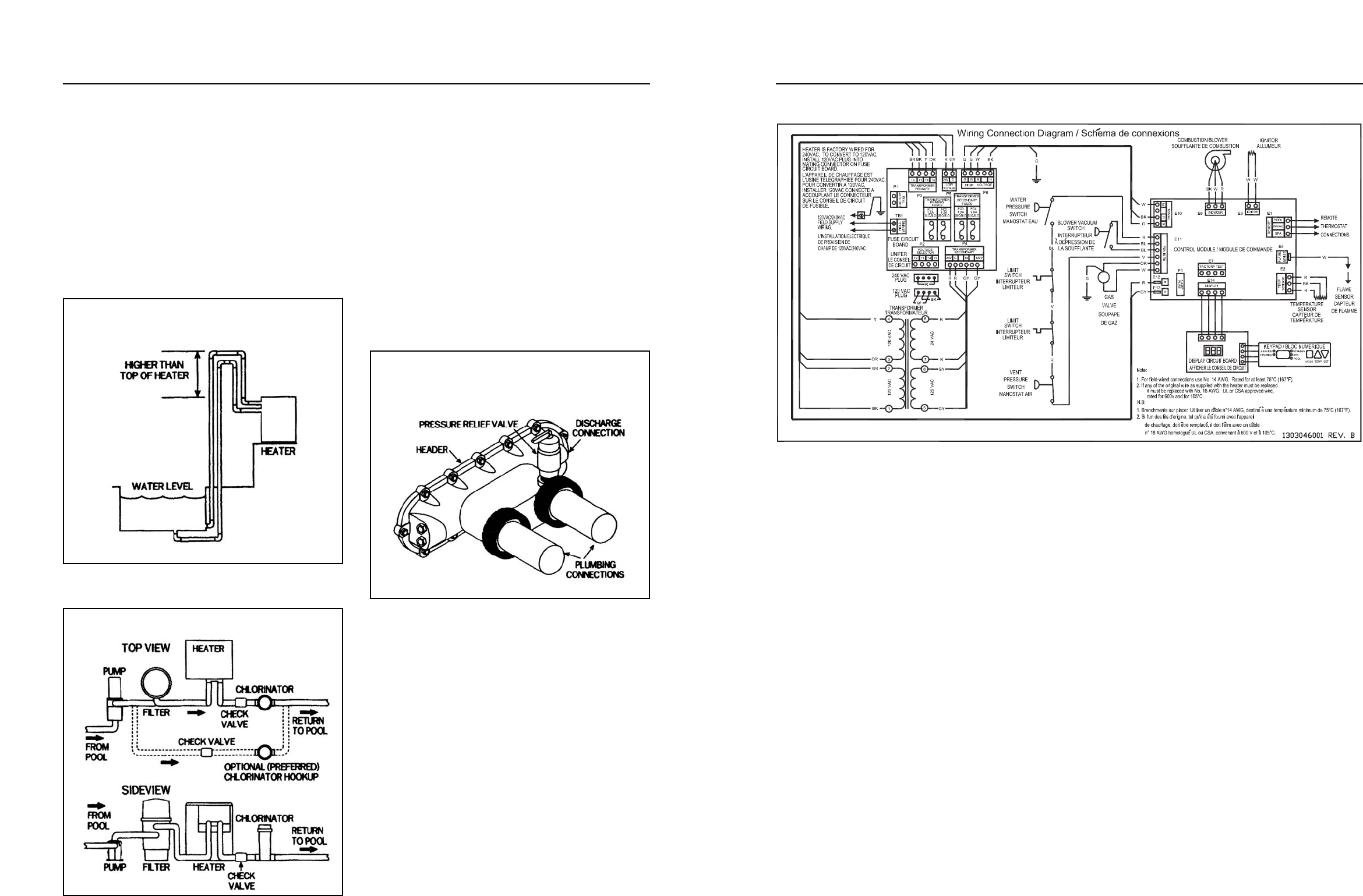
Wiring Diagram Figure 35
Electrical connections:
The heater is equipped with a Hot Surface Ignition
Control System that automatically lights the burners.
An external power supply is required to power the
control system.
The heater comes factory-wired for use with a 240
VAC, 60 Hz, field power supply. To convert the heater
to 120 VAC, 60 Hz, remove the 240 VAC Voltage
Selector Plug from the receptacle on the Fuse Board.
Locate the 120 VAC Voltage Selector Plug and install
it into the receptacle.
All wiring connections to the heater must be made
in accordance with the latest edition of the National
Electrical Code
ANSI/NFP
A
70, unless local code
requirements specify otherwise. In Canada, follow CSA
C22.1 – CANADIAN ELECTRICAL CODE, Part 1.
The heater must be electrically grounded and
bonded in accordance with local codes, or in the
absence of local codes, with National Electrical Code,
ANSI/NFPAA 70.
The H-Series heater must be installed with the
electrical connections, service entry/remote control,
located on the left side of the heater.
Field wiring connections are to be made to the
Fuse Board behind the control access panel. Connect
the field supply wires to the terminal block on the
Fuse Board. Connect the ground wire to the lug adja-
cent to the Fuse Board. Tighten terminal screws to 8
in-lbs.
17
Installation above pool/spa surface:
I
f the heater is installed less than three (3) feet
a
bove the surface of the pool/spa water, install eye-
ball fittings or directional flow fittings on the end of the
return water line to the pool/spa to create adequate
backpressure at the heater to operate the pressure
safety switch when filter pump is running.
If heater is installed more than three (3) feet above
the surface of pool/spa water, install a loop as shown
on Figure 32 to prevent drainage of water in heater
during filter change.
For installation below pool/spa surface, refer to
Section IV.
Automatic chlorinators and chemical feeders:
If used, a chlorinator must be installed down-
stream from the heater in the pool return line and at a
lower elevation than the heater outlet connection. See
Figure 33. Install a separate positive seal, corrosion
resistant check valve between the heater outlet and
chlorinator to prevent highly concentrated sanitizers
from back-siphoning into the heater. Back-siphoning
usually occurs when the pump is shut off and a pres-
sure-section differential is created.
Pressure relief valve:
It may be necessary to install a pressure relief
valve to conform with local building codes. A
3
⁄4” pres-
sure relief valve with a discharge capacity greater
than or equal to the BTUH input of the heater and a
pressure relief rating less than the heater working
pressure is recommended (see rating plate).
A
3
⁄4” NPT
connection is provided in the front head
-
er for installation of a pressure relief valve. See
Figure 34. The valve shall be installed directly to the
header in a vertical position.
T
o avoid scalding or
water damage due to relief valve operation, connect
a drain pipe to the valve outlet and run the line to a
safe place of discharge. The drain pipe must be at
least the same size as the valve discharge connec-
tion throughout its entire length and must pitch down-
ward from the valve. No shutof
f valve or restriction
shall be installed between the relief valve and the
discharge of the drain line. The valve lever should be
lifted at least once a year to ensure that the water
-
way is clear.
16
Heater Installation Above Pool
Figure 32
Automatic Chlorinator
Figure 33
Pressure Relief Valve
Figure 34


