5. Turn on water system and start heater follow
ing the lighting instructions on the label inside
the cabinet. If there is more than just the
pool/spa heater connected to the gas supply
line, turn each of those appliances on while
testing the heater.
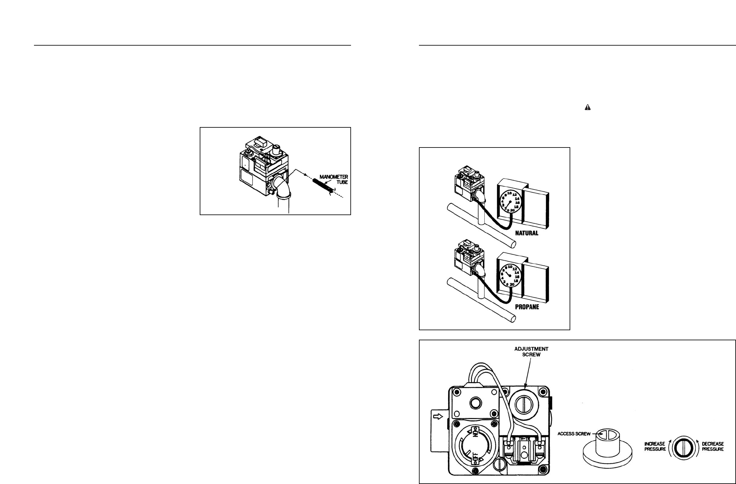
6. Take pressure reading with the heater running.
Propane gas must have 7” W.C. (water
column pressure). Natural gas must have 2”
W.C. See Figure 38.
7. If the gas pressure does not meet the above
requirements the regulator must be adjusted.
B. Gas pressure regulator adjustment procedure:
1. Remove access screw from the pressure
regulator.
2. Turn regulator adjustment screw clockwise to
increase pressure and counterclockwise to
decrease pressure. Replace access screw.
See Figure 39.
SAFETY WARNING: Do not remove the
1
⁄8” pipe
nipple with the valve in the “ON” position. The valve
must be in the “OFF” position when the plug is
remove.
3. Remove the
1
⁄8” pipe nipple and replace
1
⁄8”
plug. If proper pressure cannot be achieved
by adjusting the regulator, the installer must
contact the gas supplier and request that the
inlet pressure to the heater be set as follows:
Natural gas – 7” W.C., Propane gas – 11”
W.C. The inlet gas pressure must not exceed
10.5” W.C. (water column pressure) for
Natural gas or 13 W.C. for Propane gas.
Exposure to higher pressures can damage
the gas control valve, causing leaks or
diaphragm rupture. This damage could result
in fire, explosion, or burner overfiring leading
to carbon monoxide poisoning. Minimum inlet
gas pressure is 4.5” W.C. for Natural and 9”
W.C. for Propane for the purpose of input
adjustment.
21
Section IV. Installer Check-out And Start-up
General:
S
ome of the following procedures will require the
h
eater to be operating. Full lighting and shutdown
instructions are included on the lighting instructions
label secured inside the cabinet. The heater is auto-
matically lit on each call for heat.
Water must be flowing through the heater during
operation. Check that the pump is operating and the
system is filled with water and purged of all air prior
to starting heater.
Gas line testing:
The appliance and its gas connection must be leak
tested before placing the appliance in operation. The
heater and its individual shutoff valve must be discon-
nected from the gas supply piping system during any
pressure testing of that system at test pressures in
excess of
1
⁄2 psig (3.45 kPa). The heater must be iso-
lated from the gas supply piping system by closing its
individual manual shutoff valve during any pressure
testing of the gas supply piping system at test pres-
sure equal to or less than
1
⁄2 psig (3.45 kPa).
Gas supply line must be capped when not con-
nected. After pressure testing, reconnect the gas pip-
ing to the gas valve. Turn gas supply on and test all
pipe and tubing joints for leaks. Use a soap and water
solution. Bubbles forming indicate a leak. Never use
a open flame (match, lighter, torch, etc.) as a leak
could cause an explosion or injury. Shut off gas
and fix even the smallest leak right away. Be sure to
leak test manifold fittings using above procedure once
heater is in operation.
Gas pressure test procedure:
The following gas pressure requirements are
important to the proper operation of the burners in
gas heaters. Improper gas pressure or gas volume
will create the following conditions:
1. Flame burns totally yellow.
2.
Flame lifts off burner.
3. Heat exchanger soots up.
The pressure regulator on all H-Series heaters is
preset at the factory and normally needs no adjust-
ment. If gas pressure is inadequate, check for under
-
size piping between meter and heater or for low
capacity gas meter.
A. Gas pressure test procedure:
1. Obtain necessary equipment:
a. Manometer to read pressure in inches of
water column.
b. 1/8” nipple (1/8” pipe thread x 1” long).
c. 3/16” Hex Wrench.
d. Screwdriver
.
SAFETY WARNING: Do not remove the
1
⁄8” plug with
the gas valve in the “ON” position. The gas valve
must be in the “OFF” position when the plug is
removed.
2. Remove
1
⁄8” plug from gas valve.
3. Install
1
⁄8” pipe nipple into gas valve.
4. Attach manometer to the ” pipe nipple.
See Figure 37.
20
G
as Pressure
Figure 37
Gas Pressure Reading
Figure 38
Valve Adjustment Screw
Figure 39


