


GB
16
1740517
ting performance decreases or the quality of cut
is poor, make the following changes.
1. When you mow, make sure the throttle con-
trol is in the FAST position.
2. (Figure 8) Move the blade rotation control (1)
to the DISENGAGE position (8).
3. Stop the engine. Disconnect the spark plug
lead.
4. Check the blade(s). Keep a sharp edge on
the blade(s). A blade that is not sharp will
cause the tips of the grass to become brown.
5. If the quality of cut has not improved, replace
the mower drive belt. See “How To Replace
The Mower Drive Belt”. If the replacing the
belt does not correct the problem, take the
unit to an authorised Hayter dealer.
6. Move the blade r otation control (1) to the
DISENGAGE position (8). Stop the engine.
Disconnect the spark plug lead.
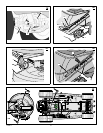
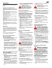
7. (Figure 16) Check the operation of the blade
brake. Rotate the pulley with your hand.
Make sure that the brake pad (7) is pressed
tightly against the pulley.
WARNING: If the brake pad (7) does
not press tightly against the pulley,
take the unit to an authorised
Hayter dealer.
8. (Figure 8) Move the blade rotation control
(1) to the ENGAGE position (9).
9. (Figure 16) Check the pads for the blade
brake (7). If the pads are excessively worn
or damaged, replace the brake pad assem-
blies. Correct replacement parts and assist-
ance are available from an authorised Hayter
dealer.
10.Attach the spark plug lead. Mow for a short
distance and again check the operation of
the blade rotation control.
11.When you move the blade rotation control to
the DISENGAGE position, all movement will
stop within five seconds. If there is move-
ment of the belt or the blades continue to ro -
tate, engage and disengage the blade
rotation control five times to remove any ex-
cess rubber from a new mower drive belt. If
you need assistance, take the unit to an au -
thorised Hayter dealer.
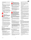
How To Adjust The Shift Lever
(Figure 17)
If the NEUTRAL position on the shift lever does
not match neutral on the gearbox, adjust the
shift lever as follows.
1. Stop the engine.
2. Disconnect the adjuster nut (2) from the
shifter yoke (3).
3. Make sure the shift lever is in the NEUTRAL
position.
4. Push the unit forward. Make sure the gear-
box is in neutral.
5. To align the adjuster nut (2) with the hole in
the shifter yoke (3), turn the adjuster nut
(2).
6. Connect the adjuster nut (2) to the shifter
yoke (3).
7. Make sure the NEUTRAL position on the
shift lever matches neutral on the gearbox.
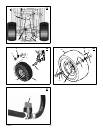
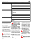
How To Check And Adjust The Clutch
(Figure 18)
If the motion drive belt is loose, the clutch will
slip when; going up a hill, pulling a heavy load,
or the unit will not move forward. Adjust the
clutch as follows.
WARNING: Before you make an in-
spection, adjustment, or repair to
the unit, disconnect the spark plug
leadg to prevent the engine from starting
by accident.
1. Check the routing of the motion drive belt.
Make sure the belt is installed correctly and
is inside all the belt guides.
2. Remove the cotter pin (1), washer (2), and
brake spring (3) from the adjustable nut
(4).
3. Disconnect the adjustable nut (4) from the
brake lever assembly (5).
4. Align the hole in the brake lever (5) with the
rear of the slot in the frame.
5. Push the clutch rod (6) toward the rear. Turn
the adjustable nut (4) until the nut will fit
through the hole in the brake lever (5).
6. Assemble the adjustable nut (4) to the
brake lever (5) and to the brake spring (3).
Fasten with the washer (2) and cotter pin
(1).
7. If the belt still slips after the clutch has been
adjusted, then the motion drive belt is worn
or damaged and must be replaced. See
“How To Replace The Motion Drive Belt”.
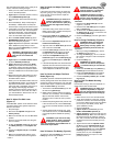
How To Check And Adjust The Drive
Brake (Figure 19)
Completely push the clutch/brake pedal forward.
Set the parking brake. Move the shift lever to the
neutral (N) position and push the unit. If the rear
wheels rotate, adjust or replace the brake pads.
Adjust the drive brake (1) as follows.
1. The location of the drive brake (1) is on the
left side of the gearbox (3).
2. Make sure the parking brake is set and the
shift lever is in neutral (N). Turn the hex nut
(2) in a clockwise direction until the rear
wheels do not turn when the unit is pushed
forward.
3. Release the parking brake and push the unit.
If the unit does not roll, turn the hex nut (2)
in a counter--clockwise direction until the unit
rolls.
4. Set the parking brake. Push the unit. If the
rear wheels do not turn, the drive brake (1)
is correctly adjusted. Release the parking
brake.
WARNING: If you cannot correctly
adjust the drive brake, replace the
brake pads. Correct replacement
parts and assistance are available from an
authorised Hayter dealer.
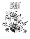
How To Remove The Battery (Figure 5)
To charge or clean the battery (1), remove the
battery (1) from the unit as follows.
WARNING: To prevent sparks, dis-
connect the black battery cable (8)
from the negative (--) terminal be-
fore you disconnect the red cable (5).
WARNING: The battery contains
sulphuric acid which is harmful to
the skin, eyes and clothing. If the
acid gets on the body or clothing, wash
with water.
1. Disconnect the black cable (8) from the
negative (--) terminal.
2. Disconnect the red cable (5) from the posi-
tive (+) terminal (4).
3. To disconnect the battery retainer (2) from
the battery tray (3), push in on the lower end
of the battery retainer (2).
4. Remove the battery (1) from the right side of
the unit.
How To Charge The Battery (Figure 5)
WARNING: When you charge the
battery, do not smoke. Keep the
battery away from any sparks. The
fumes from the battery acid can cause an
explosion.
1. Before you charge the battery (1), remove
the battery (1) from the unit.
2. To charge the battery (1),usea12voltbat-
tery charger. Charge at a rate of 6 amperes
for 1 hour.
3. Install the battery (1).
WARNING: To prevent sparks,
fasten the red cable to the positive
(+) terminal before you connect the
black cable.
4. Fasten the red cable (5) to the positive (+)
terminal (4) with the fasteners as shown.
5. Fasten the black cable (8) to the negative
(--) terminal with the fasteners as shown.
6. Connect the battery retainer (2) to the bat-
tery tray (3).
How To Level The Mower Ho using
(Figure 20)
If the mower housing is level, the blade will cut
easier and the lawn will look better.
WARNING: Before you make an in-
spection, adjustment, or repair to
the unit, disconnect the spark plug
lead to prevent the engine from starting by
accident
1. Make sure the unit is on a hard flat surface.
2. Check the air pressure in the tyres. If the air
pressure is incorrect, the mower housing will
not cut level. Make sure the tyres are inflated
to: Front Tyres 0,97 BAR (14 PSI), Rear
Tyres 0,69 BAR (10 PSI).
3. Open the cover (5).
4. (Figure 20) Move the lift lever (1) to the
LEVEL ADJUSTMENT position (2).
5. (Figure 20 and 21) Loosen the front and rear
adjuster knobs (4). Make sure both sides of
the mower housing are setting on a flat sur-
face. Also, make sure the lift links and adjust-
er plates are loose and can easily move up
or down.
6. Tighten the front and rear adjuster knobs
(4). Make sure the adjuster knobs (4) are
tight. If necessary, use a wrench to tighten
the adjuster knobs (4). For plastic adjuster
knobs (4), tighten to a torque of 7 foot
pounds (9,5 N--m). For metal adjuster
knobs (4), tighten to a torque of 10 foot
pounds (13,5 N--m).