."
...
.
ij
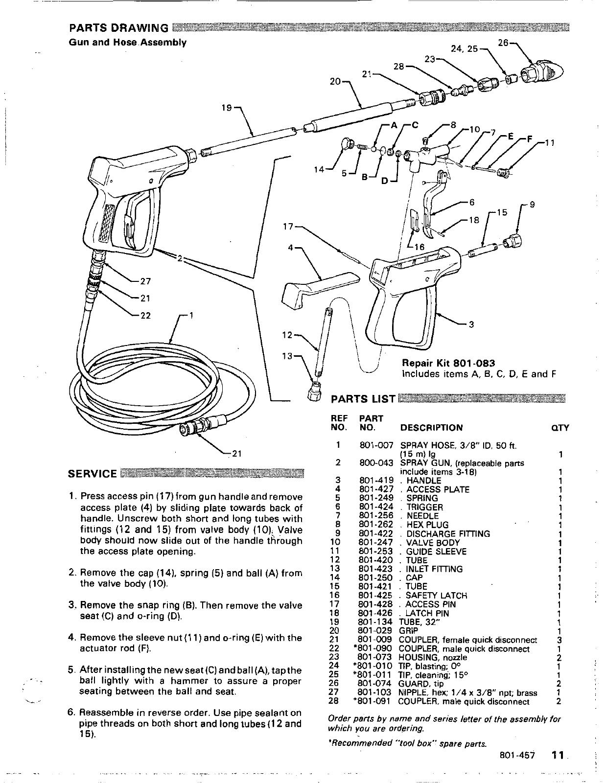
Repair
Kit
801
-083
Includes items
A,
B.
C,
D,
E
and
F
/A)
))
L
@
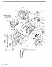
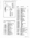
PARTS LIST
k21
SERVICE
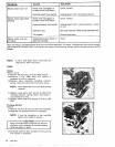
1.
Pressaccesspin(17)fromgunhandleandremove
access plate
(4)
by sliding plate towards back
of
fittings (12 and
15)
from
valve body
(10);
Valve
handle. Unscrew both short and long tubes with
body should now slide out
of
the handle through
the access plate opening.
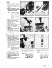
2. Remove the cap (14). spring
(5)
and ball
(A)
from
the valve body
(10).
3.
Remove the snap ring
(e).
Then remove the valve
seat
(C)
and O-ring
(13).
4.
Remove the sleeve nut
(1 1)
and O-ring
(E)
with
the
actuator rod
(F).
5.
Afterinstallingthenewseat(C)andball(A),tapthe
seating between the ball and seat.
ball lightly
with
a
hammer to assure a proper
6.
Reassemble
in
reverse order. Use pipe sealant on
pipe threads on both short and long tubes(l2 and
151.
RE
N<
:F
PART
).
NO. DESCRIPTION
an
5
6
7
8
10
11
13
12
14
15
16
17
9
18
19
21
20
22
..
23
24
25
26
27
28
801
-007
800-043
801-250
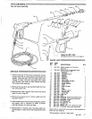
SPRAY HOSE,
3/8"
ID,
50
ft.
SPRAY GUN,
(replaceable
parts
include
items
3-18)
HANDLE
ACCESS PLATE
SPRING
TRIGGER
.
NEEDLE
(1
5
m)
IQ
.
HEX
PLUG
.
DISCHARGE FllTlNG
.
VALVE BODY
.
GUIDE SLEEVE
.
TUBE
.
INLET FllTlNG
.
CAP
'801 -090
801 -073
'801 -01
0
"801 -01 1
801 -074
801-103
*a01
-091
.
.
SAFETY LATCH
.
ACCESS PIN
.
LATCH PIN
TUBE,
32"
COUPLER,
female quick disconnect
GRIP
HOUSING,
nozzle
COUPLER,
male
quick disconnect
TIP,
cleaning;
150
TIP,
blasting;
0"
GUARD,
tip
NIPPLE,
hex; 1/4
x
3/8"
npt;
brass
COUPLER,
male quick disconnect
1
1
1
1
1
1
1
1
1
1
1
1
1
Order parts by name
and
series
letter
of
the assembly
for
which
you
are
ordering.
*Recommended
"tool
box" spare
parts.
801.457
11
.
.
..
_.


