


7
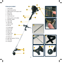
Assembly
It is necessary to attach the
upper and lower shafts, fit the
blade or spool head and the
appropriate safety guard and
attach the secondary handle.
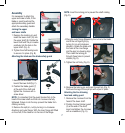
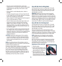
Joining the upper
and lower shafts
1. Depress the location pin and
insert the lower shaft (10) into
the upper shaft (9). Rotate the
lower shaft until the pin locates
positively into the hole in the
upper shaft.
(Fig. A).
2. Tighten the shaft locking knob
to secure it in place
(Fig. B).
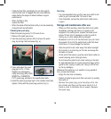
Attaching the blade and the blade safety guard
1. Remove the 4 screws in the
head of the lower shaft (Fig. C).
2. Position the blade guard (7)
at the end of the shaft and
tighten the 4 screws with a
screw driver.
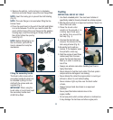
NOTE. It is important that the guard locates fully in the
head of the lower shaft and then all 4 screws are fully
tightened. Failure to do this may prevent the blade from
rotating correctly.
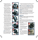
3. Remove the split pin, nut (by turning in a clockwise
direction) and outer flange. With the inner flange still fitted
on the shaft, fit the blade on to the hub of the flange.
NOTE. Insert the locking pin to prevent the shaft rotating
(Fig. D).
4. Place the outer flange followed by the nut on to the blade
and fit the nut finger tight (by
turning it in an anti-clockwise
direction). Rotate the blade until
the holes of the inner flange
and the gear box housing align.
Then insert the locking pin
through these holes to prevent
rotation (Fig. D).
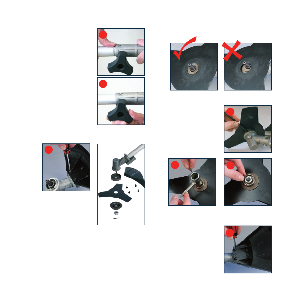
5. Tighten the nut firmly. (Fig. E).
6. Remove the locking pin and insert the split pin (Fig. F).
Fold over the legs of the split pin with a pair of pliers.
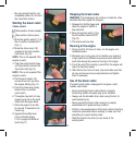
Attaching the line trimming
head and safety guard
1. Remove the 4 screws from the
head of the lower shaft.
2. Position the line trimmer guard
(3) at the end of the shaft,
insert and tighten the 4 screws
with a screwdriver
(Fig. G).
A
B
C
E
F
D
G