


9
Setting up
CAUTION. Never carry out any assembly operations or
adjustments with the power connected to the mower. Always
ensure that the power button is in the off position and that
the power plug is disconnected from the supply.
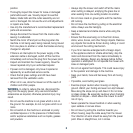
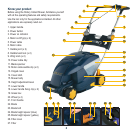
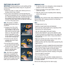
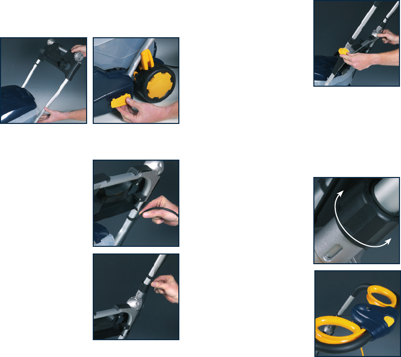
1. Ensure that the handle is in the correct orientation i.e.
the cable tidy (10) must be on the uppermost side of the
lower handle (17) as shown on
the main photograph. Fit the
two tubes of the lower handle
(17) into the slots in the mower
body (15).
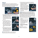
2. Fix the ends of the lower
handle in position with the two
lower handle fixing clips (18).
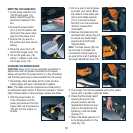
3. Using the two saddle clips
(12), secure the black-coloured
motor cable (6) to the upper
handle (1) and lower handle
(17).
4. Fit the handle joints (7) of the
upper handle (1) over the die-
cast ends of the lower handle
(17) and secure them together
with the wing knobs (9).
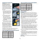
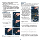
Note. There are two spacers under the blade, one
coloured blue (24) and one coloured yellow (25).
5. The blue spacer can be removed to increase the
incremental cutting heights by an extra 6mm at all
5 settings of the height
adjustment lever (16). The
mower must not be operated
without the yellow spacer (25)
in position under the blade.
Instructions on how to remove
the blue spacer are given in
the section on changing the
mower blade.
CAUTION. Keep the two arms of the upper handle (1)
parallel and insert them into the handle joints, both at the
same time. If you insert one arm and then the other, you
may damage the joints. When removing the handle, keep
the arms parallel and remove both arms at the same time.
Ensure that each arm of the upper handle (1) is properly
seated in the handle joints (7) as follows:
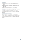
1. Loosen the two handle twist
locks (8).
2. Keeping the two arms of the
upper handle parallel, make
sure that the upper handle
(1) is fully inserted into the
handle joints (7).
3. Retighten the two handle
twist locks (8) turning them
clockwise.
Note. Make sure that the
switchbox is facing upwards.