


14
The system ready LED will be OFF when the switch
is in the manual or OFF positions.
The system ready LED is also used to indicate the
presence of utility sensing at the PCB when the switch
is either in the AUTO or MANUAL modes. The LED
will flash at the rate of 1/2 second on, 1/2 second off
if the utility sensing level is below the transfer back
threshold.
This secondary function is only available with dip
switch two in the OFF position (standard ATS appli-
cation).
3.3 MANUAL TRANSFER AND
START-UP
To transfer electrical loads to the Standby
(EMERGENCY) power source side and start the
engine manually, refer to the Owner’s Manual of the
particular transfer switch.
3.4 ENGINE GOVERNOR
ADJUSTMENTS
Engine speed governing is also controlled by the
engine control board. Connector J2 on the engine
control board interfaces with a governor driver mod-
ule and the Bosch throttle body. The engine gover-
nor has been set by the factory during final testing
of the generator and, in most cases, should not be
adjusted.
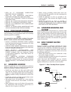
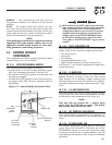
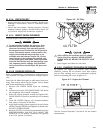
If, however, adjustments are necessary, or a new
engine control board is installed in the generator, the
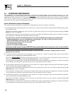
following procedure should be followed (Figure 3.2):
1. Set all three potentiometers (pots) fully counter-
clockwise.
2. Under no load condition, increase the GAIN pot
as much as possible without causing instability.
3. Apply 1/4, 1/2, 3/4 and full load to the unit.
Decrease the GAIN pot if there is instability at any
load point.
4. Under full load condition, increase the stability
pot until the unit returns to 60 Hertz (or 50 Hertz
in 50 Hertz applications).
5. Reduce load to 3/4, 1/2, 1/4 and no load. Decrease
the stability pot if there is instability at any load
point.
6. Adjust differential pot to make the recovery to
load changes even faster and minimize load
change undershoot and overshoot. If it is set too
high it may introduce oscillations at some load.
It can be set to zero (full CCW) if a small amount
causes oscillations at some load.
Figure 3.2 — Engine Governor Adjustment
PCB# 0E4906 REV.
R4
9
D17
J2
C2
C
2
6
U7
C
2
7
R44
Q2
D1
9
C30
RL1
2
L
3
LE
D
1
C4
R
2
5
C9
C
2
1
D
1
0
J1
R4
8
R1
U1
RL2
1
2
3
4
UNUSED
GTS/ATS
50/60 HZ
POSITION 1
50/60 HZ
ON = 50 HZ
OFF = 60 HZ
POSITION 2
GTS/ATS Select
ON = GTS
OFF = ATS (standard mode)
STABILITY
DIFFERENTIAL
DIP SWITCH
0
0
3.5 RETRANSFER AND SHUTDOWN
When utility power source voltage has been restored,
electrical loads may be transferred back to that
source and the generator can be shut down as fol-
lows:
• Verify that UTILITY power supply voltage to the
transfer switch has been positively turned OFF,
using whatever means provided (such as utility
main line circuit breaker).
• Set the generator’s main circuit breaker to its OFF
or OPEN position.
• Let the generator engine run at no-load for a few
minutes, to stabilize internal unit temperatures.
• On the generator console, set the AUTO/OFF/
MANUAL switch to OFF. Wait for engine to come to
a complete stop.
• For transfer to utility position, refer to the Owner’s
Manual of the particular transfer switch.
• Turn on the UTILITY power supply to the transfer
switch, using whatever means provided (such as
a utility main line circuit breaker). The UTILITY
power source now powers the loads.
3.6 AUTOMATIC OPERATION
To set the system for fully automatic operation, pro-
ceed as follows:
• Check that load circuits are connected to the
utility power supply.
• Set the AUTO/OFF/MANUAL switch to its AUTO
position.
• Set the generator main circuit breaker to its ON or
CLOSED position.
Section 3 — Operation
Liquid-cooled 30 kW Generators