


13
MANUAL — The control board will start and run
the generator whenever the switch is in the manual
position.
AUTO — The control board will monitor the two-
wire start circuit. When a two-wire start is issued the
control board will immediately start and run the gen-
erator. Whe the two-wire start is removed the control
board will immediately stop the generator.
NOTE:
If the generator is installed in conjunction with an
engineered GTS type transfer switch, refer to the
applicable transfer switch manual for exact oper-
ating parameters and timing sequences.
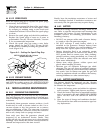
3.2 CONTROL CONSOLE
COMPONENTS
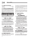
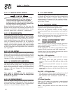
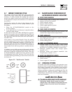
The components of a home standby generator control
console (Figure 3.1) are as follows:
3.2.1 AUTO/OFF/MANUAL SWITCH
Use this three-position switch as follows:
• Set the switch to AUTO for fully automatic opera-
tion. See “Automatic Operation” (Section 3.6).
• Set switch to MANUAL position to crank and start
the generator engine.
• Set switch to OFF position to shut down an operat-
ing engine. With OFF selected, operation will not
be possible.
Figure 3.1 - Home Standby Generator Panel
E
U
S
U
F
F
E
U
S
U
F
(
SEE OWNER'S MANUAL FOR COMPLETE LED DETAILS
)
5
FLA
S
HIN
G
RED LED'
S
= EXER
C
I
S
ER N
O
T
S
E
T
FLA
S
HIN
G
G
REEN LED = N
O
U
TILITY
S
EN
SE
TO SET EXERCISER TIME
1) PLACE AUTO/OFF/MANUAL SWITCH TO AUTO POSITION.
(
IN AUTO MODE ONLY
)
SOLID GREEN LED = SYSTEM READY, UTILITY POWER O
N
OFF
EXER
C
I
SE
TIME
ON
S
E
T
LED INDI
C
AT
O
R
S:
RED LED'
S
= INDIVID
U
AL FA
U
L
T
M
AN
U
A
L
O
F
F
A
U
T
O
0E7194
O
VER
C
RAN
K
A
U
T
O/O
FF
/
MAN
U
A
L
S
WIT
CH
1
5
A F
USE
MAI
N
P
O
WE
R
4A F
USE
BATTERY
C
HAR
G
E
R
S
E
T
EXE
C
I
S
E
R
TIME
S
WIT
CH
RED LED
G
REEN LE
D
DANGER
With switch set to AUTO, engine can crank and
start suddenly without warning. Such automatic
start up normally occurs when utility source
voltage drops below a pre-set level. To prevent
possible injury that might be caused by such
sudden starts, set AUTO/OFF/MANUAL switch
to OFF before working on or around the unit.
Then, place a “DO NOT OPERATE” tag on control
console.
3.2.2 FAULT INDICATOR LED
This LED goes ON when one or more of the following
engine faults occurs and when engine shuts down.
• Low Oil Pressure
• Overcrank
• Low Battery
• Overspeed/RPM Sensor Loss
• High Coolant Temperature/Low Coolant Level
See Section 1.7 for further explanation of engine pro-
tection functions.
3.2.3 15 AMP FUSE
Fuse protects the control console’s DC control circuit
against electrical overload. If the fuse has melted
open because of an overload, engine cranking and
startup cannot occur. If the fuse needs to be replaced,
use only an identical 15-amp replacement fuse. (Type
AGC)
3.2.4 4.0 AMP INLINE FUSE
This fuse protects the battery charger against electri-
cal overload. If the fuse needs to be replaced, use only
an identical 4 amp replacement fuse (type AG).
NOTE:
This fuse will not remove the + battery input
power from the PCB when it opens. This means
the exercise timer will not be reset.
3.2.5 SET EXERCISE TIME SWITCH
This switch allows programming the generator to
start and exercise automatically. “See Weekly Exercise
Cycle.”
3.2.6 SYSTEM READY LED
The System Ready LED (green) has two main pro-
poses. First, the LED will be ON when the AUTO/
OFF/MANUAL switch is in the AUTO position, utility
is present, and there are no system alarms. This ON
state indicates the system is fully ready for automatic
operation.
Section 3 - Operation
Liquid-cooled 30 kW Generators