


10
2.5 EMERGENCY CIRCUIT ISOLATION
METHOD
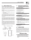
This prevents overloading the generator by keeping
electrical loads below the wattage/amperage capacity
of the generator. If the generator can only power criti-
cal loads, within it’s wattage/amperage capacity, dur-
ing utility power outages, use the emergency circuit
isolation method.
Critical electrical loads are grouped together and
wired into a separate “Emergency Distribution Panel.”
Load circuits powered by that panel are within the
wattage/amperage capacity of the generator set. The
transfer switch must meet the following require-
ments:
• It must have an ampere rating equal to the total
amperage rating of the emergency distribution
panel circuit.
• Have it installed between the building’s main dis-
tribution panel and the emergency distribution
panel.
2.6 TOTAL CIRCUIT ISOLATION
METHOD
When a generator capable of powering all electrical
loads in the circuit is to be installed, use the “Total
Circuit Isolation Method.” It is possible for the gen-
erator to be overloaded when this isolation method is
employed. The following apply to the transfer switch
in this type of system.
• Ampere rating of the transfer switch must equal
the ampere rating of the normal incoming utility
service.
• The transfer switch is installed between the util-
ity service entrance and the building distribution
panel.
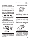
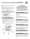
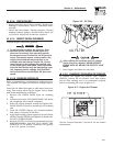
2.7 GROUNDING THE GENERATOR
The National Electrical Code requires the frame and
external electrically conductive parts of this equip-
ment to be properly connected to an approved earth
ground and/or grounding rods. For that purpose, a
GROUND LUG (Figure 2.2) is provided on the gen-
erator mounting base. Consult a qualified electrician
for grounding requirements in the area. Grounding
procedures must meet local regulations.
Figure 2.2 – Generator Grounding Lug (typical)
G
R
OU
NDIN
G
L
UG
DANGER
Do not connect the ground wire to any pipe
that carries a flammable or explosive substance
– FIRE or an EXPLOSION may result.
Proper grounding helps protect personnel against
electrical shock in the event of a ground fault condi-
tion in the generator or in connected electrical devic-
es. In addition, grounding helps dissipate static elec-
tricity that often builds up in ungrounded devices.
2.8 GENERATOR AC NEUTRAL
CONNECTIONS
The manufacturer uses an UNGROUNDED AC neu-
tral. Grounding is recommended only at the main
service entrance. If the neutral wire is grounded and
one of the phase loads becomes grounded, the exces-
sive current opens the load circuit breaker or col-
lapses the generator field. The actual result depends
on the electrical characteristics of the particular
installed generator.
Failure to connect the generator neutral proper-
ly will result in unbalanced line-to-neutral volt-
ages. Resulting high voltages will cause equip-
ment damage.
2.9 TRANSFER SWITCH SIGNAL
CONNECTIONS
2.9.1 PRE-PACKAGED ATS
If the generator is to be installed with a pre-packaged
(non-control board based) transfer switch, it is nec-
essary to connect the control wires to the generator
and set position two of the four-position dip switch
to OFF.
Setting switch two to OFF allows the control PCB to
perform the ATS control functions.
Section 2 — Installation
Liquid-cooled 30 kW Generators