


12
2.11.1 PRIOR TO INITIAL START-UP
Prior to initially starting the generator, it must
be properly prepared for use. Any attempt to
crank or start the engine before it has been
properly serviced with the recommended types
and quantities of engine fluids (oil, coolant, fuel,
etc.) may result in an engine failure.
Before starting the generator for the first time, the
installer must complete the following procedures. For
follow-up maintenance information and/or service
intervals, please refer to Section 4, “Maintenance.”
2.11.2 TRANSFER SWITCH
If this generator is used to supply power to any elec-
trical system normally powered by an electric utility,
the National Electrical Code requires that a transfer
switch be installed. The transfer switch prevents elec-
trical backfeed between two different electrical sys-
tems (for additional information, see the applicable
transfer switch manual for this unit). The transfer
switch, as well as the generator and other standby
components, must be properly located and mounted
in strict compliance with applicable codes, standards
and regulations.
2.11.3 FUEL SYSTEM
Make sure the fuel supply system to the generator (a)
delivers the correct fuel at the correct pressure and (b)
is properly purged and leak tested according to code.
No fuel leakage is permitted. See “Specifications”
(Section 1.10) for more information.
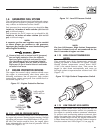
2.11.4 GENERATOR SET LUBRICATION
Check the engine crankcase oil level before operating
and add oil to the proper level – the dipstick “FULL”
mark. Never operate the engine with the oil level
below the dipstick “ADD” mark. See “Specifications”
(Section 1.10) and “Engine Oil Recommendations”
(Section 1.14).
NOTE:
This engine is shipped from the manufacturer
with 5W-20 oil. This oil should be changed after
30 hours of operation.
2.11.5 ENGINE COOLANT
Have the engine cooling system properly filled with
the recommended coolant mixture. Check the system
for leaks and other problems. See “Specifications”
(Section 1.10) and “Coolant” (Section 1.15).
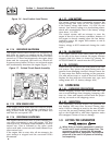
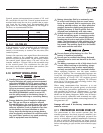
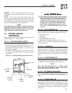
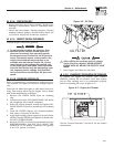
2.11.6 BELT TENSION
Check-the engine-fan belt tension and condition prior
to placing the unit into service and at recommended
intervals. Belt tension is correct when a force of
approximately 22 pounds (10 kg), applied midway
between pulleys, deflects the belt about 3/8- to 5/8-
inch (10 to 16 mm).
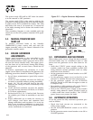
2.11.7 ELECTRICAL SYSTEM
Make sure the generator is properly connected to an
approved earth ground and/or ground rod.
Make sure the generator battery is fully charged,
properly installed and interconnected, and ready for
use.
Check to ensure that there are no loose electrical con-
nections. Restrain any loose wires to keep them clear
of any moving generator set components.
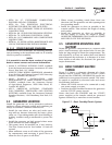
3.1 USING AN ENGINEERED “GTS”
TRANSFER SWITCH
When required, the pre-packaged standby generator
can be installed with an engineered “GTS” type auto-
matic transfer switch.
In this application, the GTS is responsible for utility
sensing, weekly exercising, and load transferring.
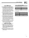
Position two of the four-position dip switch is used to
turn over this control to the GTS.
Pos2 ON — GTS Application
• The generator’s control board will NOT monitor
utility.
• The control board will NOT perform a weekly
exercise. (The five red LEDs will not flash in this
mode.)
• The control board will NOT activate the transfer
output.
• The control board WILL monitor all engine condi-
tions and shut down on all the faults listed in this
document.
Pos2 OFF — ATS Application
• The generator’s control board will perform all of
the automatic features listed in this document.
• The two-wire start connections should NOT be
used.
GTS Mode Operation
When in GTS mode, the generator’s control board
will respond as follows based on the AUTO/OFF/
MANUAL switch position.
OFF — The generator will not start and run in this
position.
Section 3 — Operation
Liquid-cooled 30 kW Generators