


SSeeccttiioonn 77
DDIIAAGGNNOOSSTTIICC TTEESSTTSS
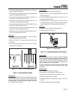
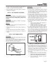
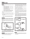
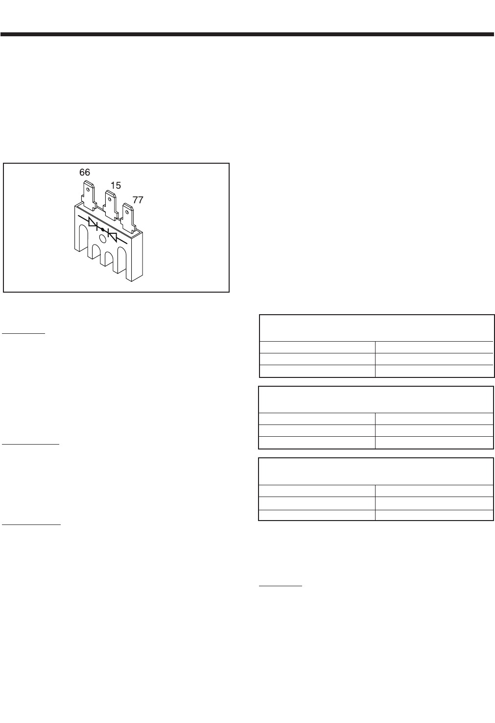
Short to Ground:
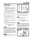
4. Set the VOM to measure resistance. Connect the positive (+)
test lead to the case housing of the BCR. Connect the negative
(-) test lead to an outer terminal. “Infinity” should be measured.
Now connect the negative test lead to the BCR center terminal.
“Infinity” should be measured. Next, connect the negative test
lead to the remaining outer BCR terminal. Once again “Infinity”
should be measured.
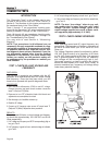
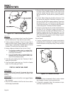
Figure 7-10. – Battery Charge Rectifier
RESULTS:
1. If any of the previous steps has failed, replace the Battery
Charge Rectifier.
2. If the BCR tests good, go to Test 17.
TEST 17 - CHECK BATTERY CHARGE
WINDINGS / BATTERY CHARGE RESISTOR
DISCUSSION:
The Battery Charge Winding (BCW) produces AC
voltage that is delivered to the Battery Charge
Rectifier. The Battery Charge Winding is a center
tapped winding consisting of the following Stator
Leads: Wire 66, Wire 77 and Wire 55. The Battery
Charge Resistor is used as a current limiting resistor.
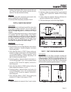
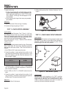
PROCEDURE:
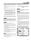
1. Disconnect the Stator Leads (Wire 66 and Wire 77) from the
Battery Charge Rectifier. (Be sure to disconnect Stator Lead
Wire 66 “Black” from Wire 66 “Blue” connector for this test).
Disconnect the Stator Lead Wire 55 from the Battery Charge
Resistor.
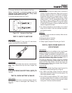
2. Set the VOM to measure resistance at the “R x 1” scale.
Connect one test lead to Stator Lead Wire 66. Connect the
other test lead to Stator Lead Wire 55. Normal Battery Charge
Winding resistance should be measured.
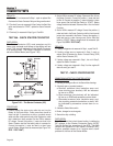
3. Connect one test lead to Stator Lead Wire 77. Connect the
other test lead to Stator Lead Wire 55. Normal Battery Charge
Winding resistance should be measured.
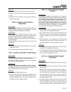
4. Connect one test lead to Stator Lead Wire 55. Connect the
other test lead to Stator Leads Wire 11 & 33 at the back of
CB1. “Infinity” should be measured.
5. Connect one test lead to Stator Lead Wire 55. Disconnect
Stator Lead Wire 2 from the DPE circuit breaker (CB3) and
connect the other test lead to Wire 2. “Infinity” should be mea-
sured.
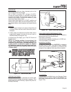
6 Connect one test lead to Stator Lead Wire 55. Connect the
other test lead to frame ground. “Infinity” should be measured.
7. Connect one test lead to the Battery Charge Resistor terminal
that Wire 55 was removed from. Connect the other test lead to
frame ground. One (1) ohm should be measured. If 1 ohm was
not measured, remove Wire 0 from the Battery Charge
Resistor. Connect one test lead to Wire 0 and the other test
lead to frame ground.
“
Continuity” should be measured. Repair
or replace Wire 0 if defective and retest the Battery Charge
Resistor.
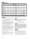
BATTERY CHARGE WINDING RESISTANCE *
QP55 (Model 4702/4703)
AACCRROOSSSS WWIIRREESS:: OOHHMMSS
55 & 66 0.100Ω − 0.116Ω
55 & 77 0.100Ω − 0.116Ω
BATTERY CHARGE WINDING RESISTANCE *
QP65 (Model 4704/4705)
AACCRROOSSSS WWIIRREESS:: OOHHMMSS
55 & 66 0.104Ω − 0.120Ω
55 & 77 0.087Ω − 0.101Ω
BATTERY CHARGE WINDING RESISTANCE *
QP75 (Model 4706/4707)
AACCRROOSSSS WWIIRREESS:: OOHHMMSS
55 & 66 0.092Ω − 0.107Ω
55 & 77 0.076Ω − 0.088Ω
* Resistance values In ohms at 20° C. (68° F.). Actual readings
may vary depending on ambient temperature. A tolerance of plus
or minus 5% is allowed.
RESULTS:
1. For Steps 2 & 3, keep in mind that the resistance values are
very low. Depending upon the quality of the VOM, it may read
“
Continuity” across these windings. Exercise good judgement
with these values.
2. If Steps 2, 3, 4, 5 & 6 fail any test, replace the Stator.
Page 46