


SSeeccttiioonn 22
MMAAJJOORR GGEENNEERRAATTOORR CCOOMMPPOONNEENNTTSS
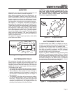
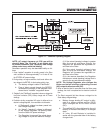
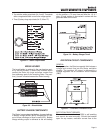
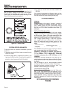
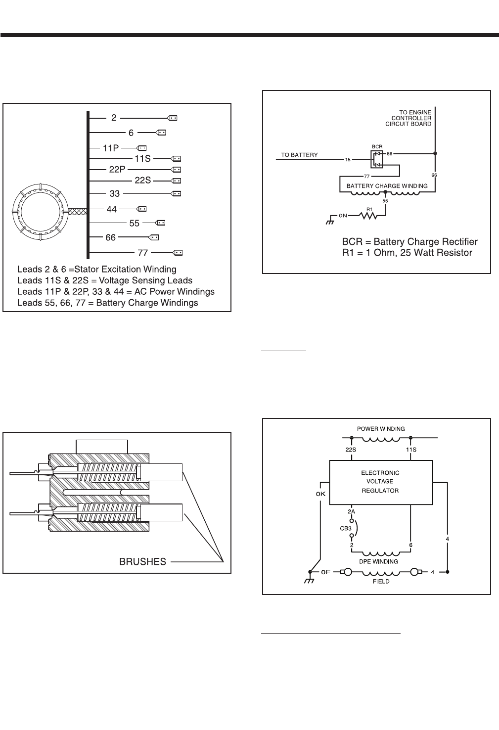
3. Two excitation winding output leads (No. 2 and 6). These leads
deliver unregulated excitation current to the voltage regulator.
4. Three (3) battery charge output leads (No. 55, 66 and 77).
Figure 2-2. – Stator Output Leads
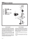
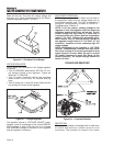
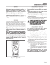
BRUSH HOLDER
The brush holder is retained in the rear bearing carri-
er by two M5 screws. It retains two brushes, which
contact the Rotor slip rings and allow current flow
from stationary parts to the revolving Rotor. The posi-
tive (+) brush is located nearest the Rotor bearing.
Figure 2-3. – Brush Holder
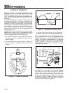
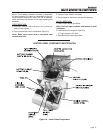
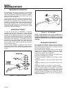
BATTERY CHARGE COMPONENTS
The Stator incorporates dual battery charge windings.
A battery charge rectifier (BCR) changes the AC out-
put of these windings to direct current (DC). Battery
charge winding output is delivered to the unit battery
via the rectifier, a 7.5 amp fuse and Wire No. 13. A 1
ohm, 25 watt resistor is connected in series with the
grounded side of the circuit.
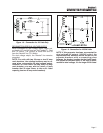
Figure 2-4. – Battery Charge Circuit
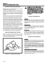
EXCITATION CIRCUIT COMPONENTS
GENERAL:
During operation, the Rotor's magnetic field induces a
voltage and current flow into the Stator excitation
winding. The resultant AC output is delivered to a
voltage regulator via an excitation circuit breaker
(CB3).
Figure 2-5. – Schematic: Excitation Circuit
EXCITATION CIRCUIT BREAKER:
The excitation circuit breaker (CB3) is self-resetting
and cannot be reset manually. Should the breaker
open for any reason, excitation current flow to the
Page 9