


SSeeccttiioonn 77
DDIIAAGGNNOOSSTTIICC TTEESSTTSS
PROCEDURE:
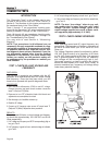
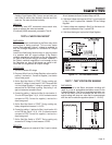
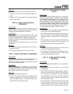
1. Disconnect Wire 4 from the Voltage Regulator (VR). (Third ter-
minal from the top of VR).
2. Connect a jumper wire to Wire 4 and to the 12 volt fused battery
positive supply Wire 15 (Wire 15 located at fuse (F1) holder).
3. Set the VOM to measure AC voltage.
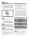
4. Disconnect Wire 2 from the DPE breaker (CB3) and connect
one test lead to that wire. Disconnect Wire 6 from the Voltage
Regulator and connect the other test lead to that wire. Start the
generator and measure the AC voltage. It should be above 60
volts. Record the results and stop the generator.
5. Re-connect Wire 2 to the DPE Circuit Breaker (CB3) and re-
connect Wire 6 to the Voltage Regulator.
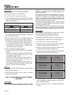
6. Disconnect Wire 11 from the Voltage Regulator (VR) and con-
nect one test lead to that wire. Disconnect Wire 22 from the
Voltage Regulator and connect the other test lead to that wire.
Start the generator and measure the AC voltage. It should be
above 60 volts. Record the results and stop the generator.
7. Re-connect Wire 11 and Wire 22 to the Voltage Regulator.
8. Remove the jumper wire between Wire 4 and 12 volt supply.
9. Set the VOM to measure DC amps.
10. Connect one test lead to the 12 volt fused battery supply Wire
15, and connect the other test lead to Wire 4 (should still be
disconnected from the VR).
11. Start the generator. Measure the DC current. Record the rotor
amp draw.
12.Stop the generator. Re-connect Wire 4 to the Voltage
Regulator.
RESULTS:
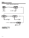
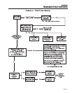
Proceed to “TEST 4 RESULTS” (top of page 40).
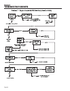
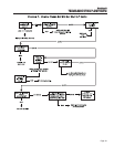
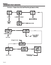
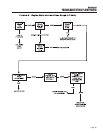
Match all results to corresponding column in the
chart. The column letter refers to the Problem 4 flow
charts on pages 28 and 29.
TEST 5- WIRE CONTINUITY
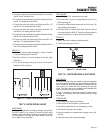
DISCUSSION:
The Voltage Regulator receives unregulated alternat-
ing current from the Stator Excitation Winding via
Wires 2, 6 and 2A. It also receives voltage sensing
from the Stator AC Power Windings via Wires 11 and
22. The regulator rectifies the AC from the Excitation
Winding and, based on the sensing signals, regulates
that DC current flow to the Rotor. The rectified and
regulated current flow is delivered to the Rotor
Brushes via Wires 4 (+) and 0 (-). This test will verify
the integrity of Wires 0 and 2A.
PROCEDURE:
1. Set a VOM to its “Rx1” scale.
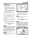
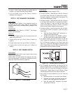
2. Remove Wire 0 from the Voltage Regulator, fourth terminal from
the top (identified by a negative (-) sign next to terminal).
3. Connect one test lead to Wire 0 and the other test lead to a
clean frame ground. The meter should read continuity.
4. Disconnect Wire 2A from the Voltage Regulator, sixth terminal
from the top. Disconnect the other end of this wire from the
Page 40
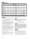
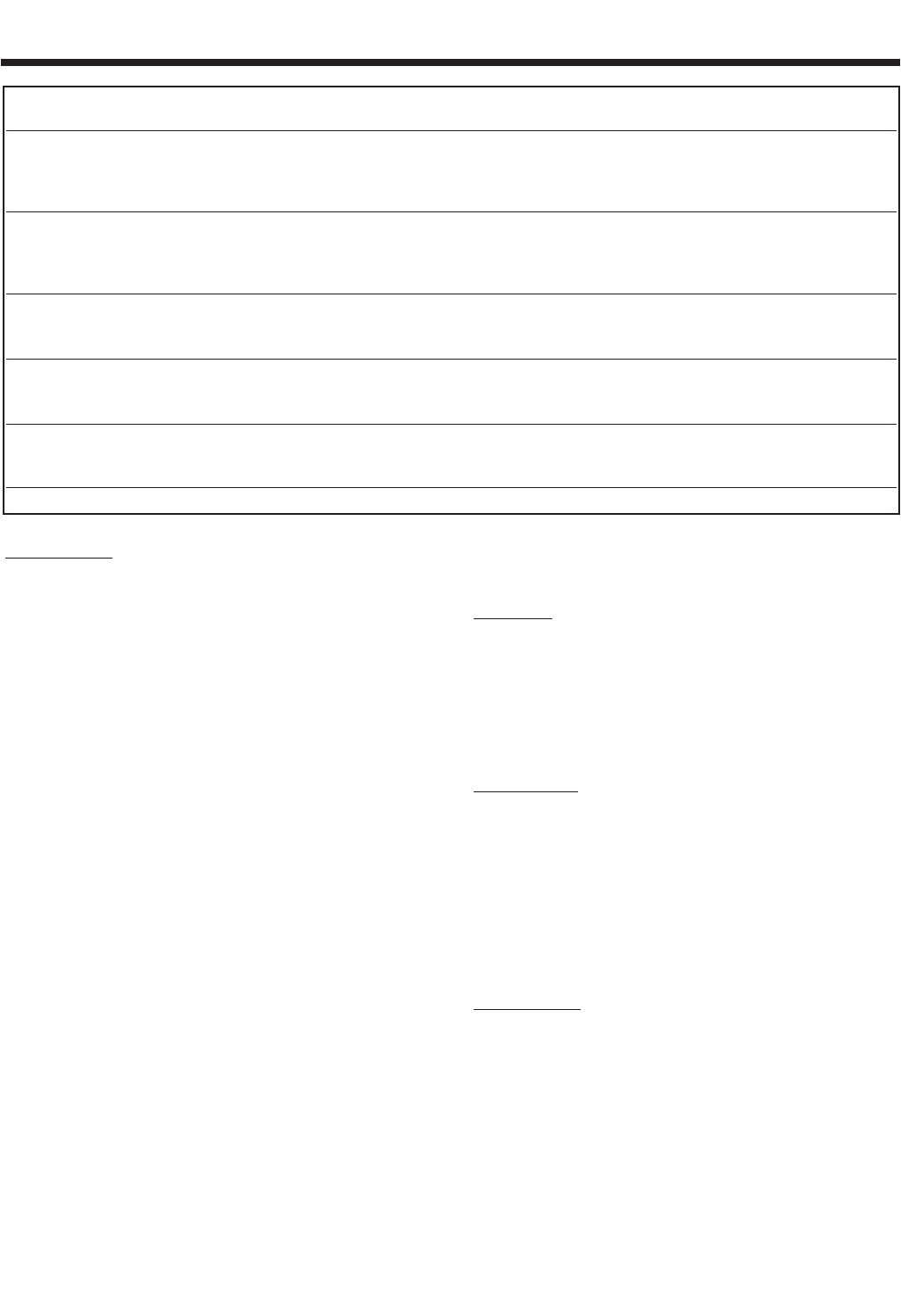
TTEESSTT 44 RREESSUULLTTSS
AA BB CC DD EE FF GG
VOLTAGE RESULTS ABOVE ABOVE BELOW ZERO OR BELOW BELOW ABOVE
WIRE 2 & 6 60 VAC 60 VAC 60 VAC RESIDUAL 60 VAC 60 VAC 60 VAC
EXCITATION WINDING VOLTAGE
(5-12 VAC)
VOLTAGE RESULTS ABOVE BELOW ABOVE ZERO OR BELOW BELOW ABOVE
WIRE 11 & 22 60 VAC 60 VAC 60 VAC RESIDUAL 60 VAC 60 VAC 60 VAC
POWER WINDING VOLTAGE
SENSE LEADS (5-12 VAC)
ROTOR AMP DRAW .85 A .85 A .85 A ZERO ≥1.2 A .85 A ZERO
QP55 ± 20% ± 20% ± 20% CURRENT ± 20% CURRENT
(MODEL 4702/4703) DRAW DRAW
ROTOR AMP DRAW 1.2 A 1.2 A 1.2 A ZERO ≥1.5 A 1.2 A ZERO
QP65 ± 20% ± 20% ± 20% CURRENT ± 20% CURRENT
(MODEL 4704/4705) DRAW DRAW
ROTOR AMP DRAW .87-.79 A .87-.79 A .87-.79 A ZERO ≥1.2 A .87-.79 A ZERO
QP75 ± 20% ± 20% ± 20% CURRENT ± 20% CURRENT
(MODEL 4706/4707) DRAW DRAW
((MMAATTCCHH RREESSUULLTTSS WWIITTHH LLEETTTTEERR AANNDD RREEFFEERR TTOO FFLLOOWW CCHHAARRTT –– PPrroobblleemm 22 oonn PPaaggeess 2288 && 2299))