


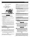
5
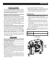
1.3 EMISSIONS INFORMATION
The Environmental Protection Agency (and California Air Resource
Board for generators certified to CA standards) requires that
this generator comply with exhaust and evaporative emission
standards. Locate the emissions compliance decal on the engine
to determine what standards the generator meets, and to determine
which warranty applies. This generator is certified to operate on
gasoline. The emission control system includes the following
components (if equipped):
• Air Induction System
– Intake Pipe / Manifold
– Air Cleaner
• Fuel System
– Carburetor
– Fuel Tank / Cap
– Fuel Lines
– Evaporative Vent Lines
– Carbon Canister
• Ignition System
– Spark Plug
– Ignition Module
• Exhaust System
– Exhaust Manifold
– Muffler
– Pulsed Air Valve
– Catalyst
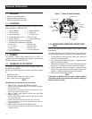
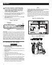
2.1 KNOW THE GENERATOR
Read the Owner’s Manual and Safety Rules before operating
this generator.
Compare the generator to Figures 2 through 4 to become
familiarized with the locations of various controls and adjustments.
Save this manual for future reference.
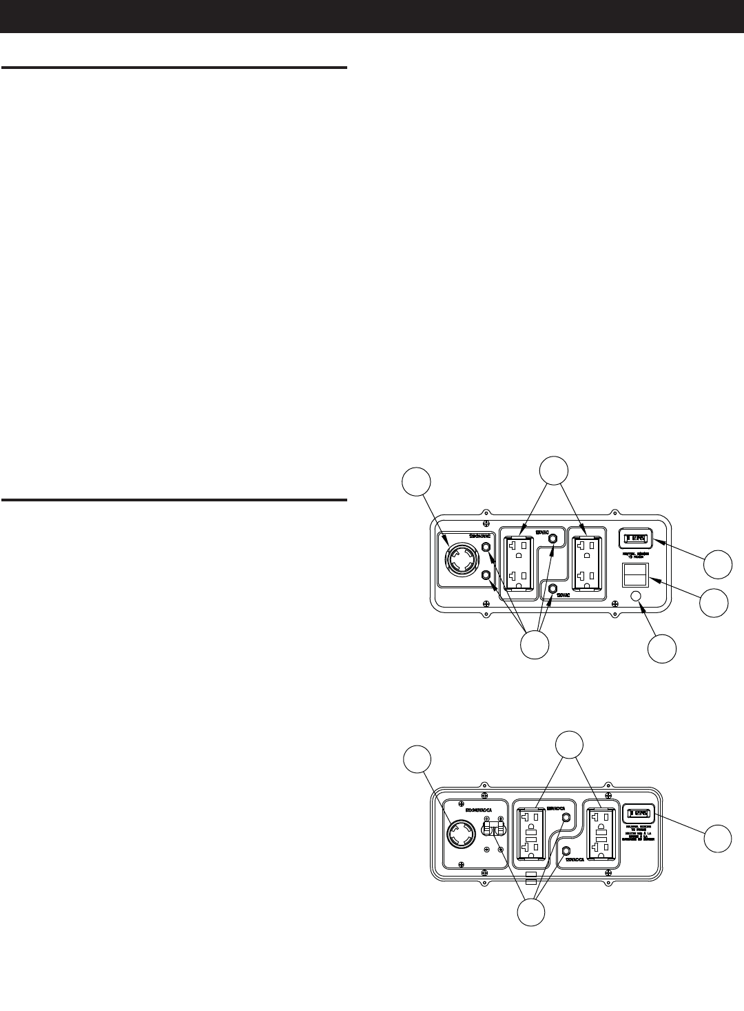
1. 120 Volt AC, 20 Amp, Duplex Receptacle – Supplies
electrical power for the operation of 120 Volt AC, 20 Amp,
single-phase, 60 Hz electrical lighting, appliance, tool and
motor loads (CARB models are equipped with GFCI outlets).
2. 120/240 Volt AC, 30 Amp Locking Receptacle – Supplies
electrical power for the operation of 120 and/or 240 Volt AC,
30 Amp, single-phase, 60 Hz, electrical lighting, appliance,
tool and motor loads.
3. Circuit Breakers (AC) – Each receptacle is provided with a
push-to-reset circuit breaker to protect the generator against
electrical overload.
4. Oil Drain – Use to drain engine oil.
5. Air Filter – Filters intake air as it is drawn into the engine.
6. Choke Knob – Used when starting a cold engine.
7. Fuel Tank – See generator Specifications for tank capacity.
8. Grounding Lug – Ground the generator to an approved earth
ground here. See "Grounding the Generator" for details.
9. Run/Stop Switch – Controls the operation of the generator
(pull start models).
9A. Start Switch – Used to start engine from the starter motor
(electric start models only).
10. Muffler – Quiets the engine.
11. Handle – Pivot and retract for storage. Press the spring-
loaded button to move handles.
12. Gas Cap – Fuel fill location.
13. Fuel Gauge – Shows fuel level in tank.
14. Oil Fill – Add oil here.
15. Recoil Starter – Use to start engine manually.
16. Fuel Shut Off – Valve between fuel tank and carburetor.
17. Roll Over Valve – Passes fuel to the engine airbox.
18. Recovery Hose – Install between the carbon canister and the
roll over valve (if equipped).
19. Hourmeter – Tracks hours of operation.
20. Battery Charger Input – This receptacle allows the capability
to recharge the 12 volt DC storage battery provided with
the 12 Volt Adaptor Plug Charger which is included in the
Accessory Box. Located behind the battery charger input is
a 1.50 Amp in-line fuse which is inside the control panel to
protect the battery (electric start models only).
21. Battery – Powers the electric starter (electric start models
only).
22. Spark Arrestor – Reduces fire hazards by containing sparks
(CARB models only).
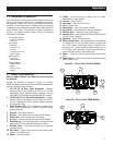
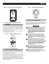
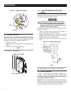
Figure 2A - Control Panel (49 State Models)
20
9A
19
2
3
1
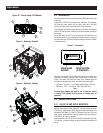
Figure 2B - Control Panel (CARB Models)
2
1
19
3
Operation