


4
1.1 UNPACKING
• Remove all packaging material.
• Remove separate accessory box.
• Remove the generator from carton.
1.1.1 ACCESSORIES
Check all contents. If any parts are missing or damaged, locate an
authorized dealer at 1-888-436-3722.
• 1 - Owner’s Manual • 1 - Handle Assembly
• 1 - Liter Oil SAE 30 • 2 - Frame Foot
• 2 - Never-Flat Wheels • 1 - 20' Power Cord
• 3 - Product Registration Cards (006110-3 only)
• 1 - Service Warranty • 1 - Emissions Warranty
• 1 - Battery Charger (Electric Start Models)
• 1 - Hardware Bag (containing the following):
– 2-Rubber Feet – 6-M8 Bolt (Long)
– 2-1/2” Axle Pins
– 2-M6 Bolts (Long)
– 2-Cotter Pins
– 2-M8 Acorn Nut
– 2-1/2” Flat Washers
– 4-Hex Flanged M8 Nuts
– 2-Hex Flanged M6 Nuts
1.2 ASSEMBLY
The generator requires some assembly prior to using it. If
problems arise when assembling the generator, please call the
Generator Helpline at 1-888-436-3722.
1.2.1 ASSEMBLING THE ACCESSORY KIT
The wheels are designed into the unit to greatly improve the
portability of the generator.
You will need the following tools to properly install the accessory
kit.
• Needle Nose Pliers
• Ratchet and 8mm, 10mm, and 13mm sockets
• 8mm, 10mm, and 13mm box wrenches
NOTE:
The wheels are not intended for over-the-road use.
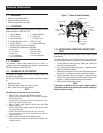
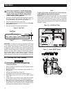
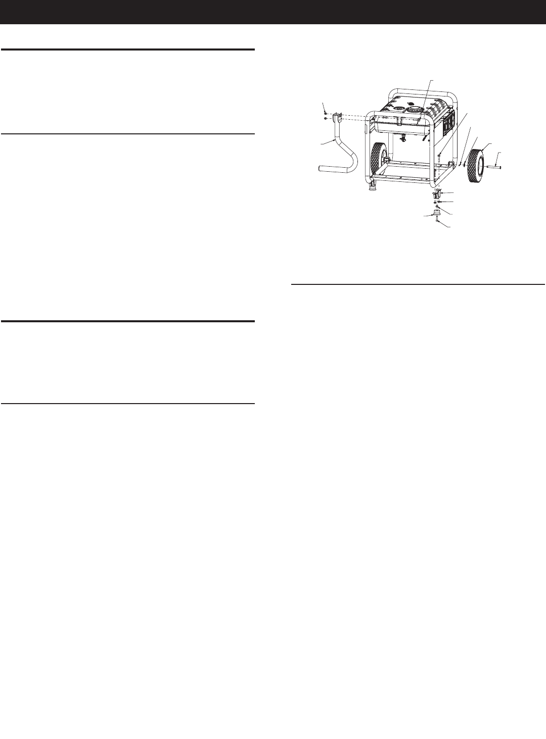
1. Refer to Figure 1 and install the Wheels as follows:
– Slide the Axle Pin through the Wheel, 1/2" Flat Washer, and Wheel
Bracket on the frame.
– Insert the Cotter Pin through the Axle Pin then bend the tabs (of the
Cotter Pins) outward to lock into place.
2. Refer to Figure 1 and install the Frame Foot and Rubber
Bumpers as shown.
– Slide the Rubber Bumper studs through the Frame Foot then install
the Locking Flange Nuts.
– Slide the Hex Head Bolts through the holes in the Frame Rail.
– Slide the Frame Foot onto the Hex Head Bolts then install the
Locking Flange Nuts.
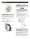
3. Refer to Figure 1 and install the Handle as shown.
– Slide the long Bolts through the Handle Bracket and Handle, then
install the Hex Nuts.
Figure 1 – Wheel & Handle Assembly
2 X RUBBER FOOT
2 X M6 BOLT
(LONG)
2 X M6 NUTS
4 X M8 NUTS
2 X FRAME FOOT
2 X AXLE PIN
2 X WHEEL
2 X 1/2” FLAT WASHER
2 X COTTER PIN
4 X M8 BOLT
(LONG)
2 X M8 BOLT (LONG)
2 X M8 ACORN NUT
HANDLE
ASSEMBLY
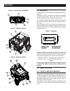
1.2.2 BATTERY CABLE CONNECTION (ELECTRIC START
ONLY)
The unit has been deliberately shipped with the battery cables
disconnected.
To connect the battery, you will need two 8mm box wrenches to
connect the battery cables. (see Figure 16 for connection details):
1. Cut off cable ties securing battery cables and remove red
covers from battery terminals.
2. First, connect the red cable to the positive (+) battery terminal
with the bolt and nut supplied.
3. Make sure connections are secure and slide rubber boot over
the positive (+) battery terminal and connection hardware.
4. Connect the black cable to the negative (-) battery terminal
with the bolt and nut supplied and slide rubber boot over the
negative (-) battery terminal and connection hardware.
5. Make sure all connections are secure.
NOTE:
If the battery is unable to start the engine, charge it with the
12V charger included in the accessory box (see the "Charging a
Battery" section for details).
General Information