


5
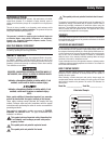
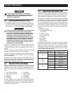
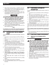
1.4 THE GENERATOR
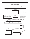
Figure 1.1 – 6kW, V-twin, GT-530 Engine
(door removed)
Air Filter External Oil Fill/Dipstick
Control
Panel
Data
Label
Circuit
Breaker
Fuel Inlet
(back)
Fuel
Regulator
Composite
Base
Battery
Compartment
Oil FilterExhaust
Enclosure
Engine Oil
Dipstick
Engine
Oil Fill
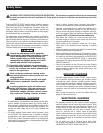
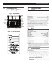
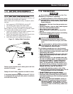
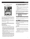
Figure 1.2 – Data Label Sample
1.5 SPECIFICATIONS
1.5.1 GENERATOR
Fuel Type ....................................................................................... LP vapor only
Rated Voltage .........................................................................................120 VAC
Rated Maximum Load Current (Amps) at 120 Volts (LP)* .............................50.0
Main Circuit Breaker ................................................................................ 50 Amp
Phase ................................................................................................................1
Number of Rotor Poles .......................................................................................2
Rated AC Frequency ....................................................................................60 Hz
Battery Requirement ........................ Group 26R, 12 Volts and 525 CCA Minimum
Weight (unit only in lbs.) ................................................................................387
Enclosure .....................................................................................................Steel
Normal Operating Range: This unit is tested in accordance to UL 2200 standards
with an operating temperature of 20 °F (-29 °C) to 122 °F. (50 °C). For areas
where temperatures fall below 32 °F (0 °C), a cold weather kit is highly recom-
mended. When operated above 104º F (40º C) there may be a decrease in engine
power. (Please reference the engine specifications section).
These generators are rated in accordance with UL2200, Safety Standard for
Stationary Engine Generator Assemblies; and CSA-C22.2 No. 100-04 Standard
for Motors and Generators.
1.5.2 ENGINE
Type of Engine .........................................................................................GT-530
Number of Cylinders ..........................................................................................2
Rated Horsepower @ 3,600 rpm* ...................................................................18
Displacement ............................................................................................. 530cc
Cylinder Block .........................................................Aluminum w/Cast Iron Sleeve
Valve Arrangement .....................................................................Overhead Valves
Ignition System .................................................................Solid-state w/Magneto
Recommended Spark Plug .....................................................................BPR6HS
Spark Plug Gap .................................................................0.76 mm (0.030 inch)
Compression Ratio.......................................................................................9.5:1
Starter .....................................................................................................12 VDC
Oil Capacity Including Filter ..........................................................Approx. 1.7 Qts
Recommended Oil Filter ............................................................. Part # 070185F
Recommended Air Filter ...............................................................Part # 0E9371
Operating RPM............................................................................................2,600
* Engine power is subject to and limited by such factors as fuel Btu content, ambi-
ent temperature and altitude. Engine power decreases about 3.5 percent for each
1,000 feet above sea level; and also will decrease about 1 percent for each 6 C
(10 F) above 16 C (60 F) ambient temperature.
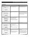
1.6 READY TO RUN
The "Ready to Run" on the display is ready when all of the following
conditions are true:
1. The AUTO/OFF/MANUAL switch is set to the AUTO position.
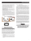
2. The utility voltage being supplied to the unit is being sensed
by the PCB. If the utility sense voltage is not connected to the
unit or if it is below approximately 150-160 volts AC, then
the system will display the message "No Utility Present". This
indicates that if the AUTO/OFF/MANUAL switch is placed in
the Auto position, the generator will start.
3. No alarms are present, for example, low oil pressure, high
temperature, etc.
General Information