


13
Operation
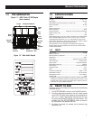
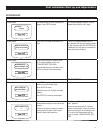
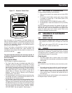
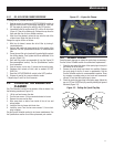
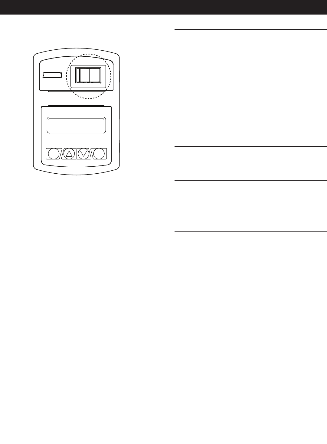
Figure 3.1 – Generator Control Panel
Escape
MAIN FUSE
AUTO OFF MANUAL
7.5 AMP
Enter
Upon first power up of the generator, the display interface will
begin an installation assistant. The assistant will prompt the user
to set the minimum settings to operate. These settings are Current
Date/Time. The maintenance intervals will be initialized when the
exercise time is entered (Figure 3.1).
If the 12 volt battery is disconnected or the fuse removed, the
Installation Assistant will operate upon power restoration. The
only difference is the display will only prompt the customer for the
current Time and Date.
NOTE:
The current date/time will need to be reset every time the 12
volt battery is disconnected and then reconnected, and/or when
the fuse is removed.
Display Interface Menus
The LCD display is organized as detailed below:
The “Home” page, this page is the default page which will be •
displayed if no keys are pressed for 30 seconds. This page
normally shows the current Status message and the current
date and time. The highest priority active Alarm and/or Warning
will be automatically posted on this page as well as flashing
the backlight when such an event is detected. In the case of
multiple Alarms or Warnings, only the first message will be
displayed. To clear an Alarm or Warning, see the Protection
Systems section - Clear Alarm.
The display backlight is normally off. If the user presses any key, •
the backlight will come on automatically and remain on for 30
seconds after the last key was pressed.
The “Main Menu” page will allow the user to navigate to all other •
pages or sub-menus by using the Left/Right and Enter keys.
This page can be accessed at any time with several presses of
the dedicated Escape key. Each press of the Escape key takes
you back to the previous menu until the main menu is reached.
This page displays the following options: HISTORY; STATUS;
EDIT; AND DEBUG. (See the Appendix - "Menu System".)
3.2 AUTOMATIC OPERATION
To select automatic operation, do the following:
1. Make sure the remote 2-wire contacts are set to their OPEN
position.
2. Be sure that normal battery charger power source voltage
is available to terminal lugs T1 and Neutral (Refer to the
Electrical Data section).
3. Set the generator’s AUTO/OFF/MANUAL switch to AUTO.
4. Set the generator’s main circuit breaker to its ON (or CLOSED)
position.
With the preceding steps complete, the generator will start auto-
matically when remote 2-wire start contacts are CLOSED (ON).
After the unit starts, loads are transferred to the generator and
charges the battery pack by the inverter system. Refer to the
Sequence of Automatic Operation section.
3.3 SEQUENCE OF AUTOMATIC
OPERATION
3.3.1 REMOTE START ON
Initial Conditions: Generator in Auto, ready to run. When remote •
start contacts are CLOSED (ON), the engine will crank and
start.
After remote start contacts OPEN (OFF), the engine will shut •
down after one (1) minute cool-down time.
3.3.2 CRANKING
The system will control the cyclic cranking as follows: 16 second
crank, seven (7) second rest, 16 second crank, seven (7) second
rest followed by three (3) additional cycles of seven (7) second
cranks followed by seven (7) second rests.
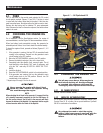
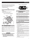
Choke Operation
1. The 530cc engines have an electric choke on the stepper
motor bracket that is automatically controlled by the electronic
control board.
Failure to Start
This is defined as any of the following occurrences during crank-
ing:
1. Not reaching starter dropout within the specified crank cycle.
Starter dropout is defined as four (4) cycles at 1,000 RPM.
2. Reaching starter dropout, but then not reaching 2200 RPM
within 15 seconds. In this case the control board will go into
a rest cycle for seven (7) seconds, then continue the rest of
the crank cycle.
During a rest cycle the start and fuel outputs are de-energized and
the magneto output is shorted to ground.