


4 Generac
®
Power Systems, Inc.
1.1 GENERATOR
This equipment is a liquid-cooled, engine-driven
generator set. The generator is designed to supply
electrical power that operates critical electrical loads
during utility power failure. The unit has been
factory-installed in a weather resistant, all metal
enclosure and is intended for outdoor installation
only. Use this generator as a source of electrical
power for the operation of 120 and/or 240VAC,
single-phase loads.
These models are available. They are rated as
follows:
Model 004912 : Provides 15,000 watts (15 kW) of single-phase
power.
Model 004913: Provides 25,000 watts (25 kW) of single-phase
power.
If this generator is used to power electrical
load circuits normally powered by a utility
power source, it is required by code to install
a transfer switch. The transfer switch must
effectively isolate the electric system from the
utility distribution system when the generator
is operating (NEC 701). Failure to isolate an
electrical system by such means results in
damage to the generator and may also result
in injury or even death to utility power
workers due to backfeed of electrical energy.
1.2 TRANSFER SWITCH
This generator system includes a matched automatic
transfer switch which is intended to be used in
conjunction with the Centurion generator. It is
supplied in a NEMA 3R enclosure. The NEMA 3R
enclosure is weather resistant and can be used
indoors or outdoors. Follow these rules:
• Install the transfer switch on a firm, sturdy
supporting structure.
• To prevent switch distortion, level the switch if
necessary. This can be done by placing washers
between the switch enclosure and the mounting
surface.
• Never install the switch where water or any
corrosive substance might drip onto the enclosure.
• Protect the switch at all times against excessive
moisture, dust, dirt, lint, construction grit and
corrosive vapors.
• It is highly recommended to utilize a
Generac/Centurion transfer switch with this
generator or it may void the warranty.
1.3 AUTOMATIC SYSTEM OPERATION
When this generator, along with its transfer switch,
has been installed and interconnected, a circuit
board in the generator panel constantly monitors
utility power source voltage. Should that voltage drop
below a preset value, and remain at such a low state
for a preset amount of time, the generator cranks and
starts. After the generator starts, the transfer switch
transfers load circuits so the generator can power
them.
When utility source voltage has been restored, the
switch re-transfers back to the utility source voltage
and the generator then shuts down.
Please reference the transfer switch manual for
specific information.
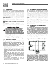
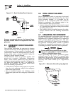
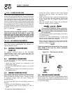
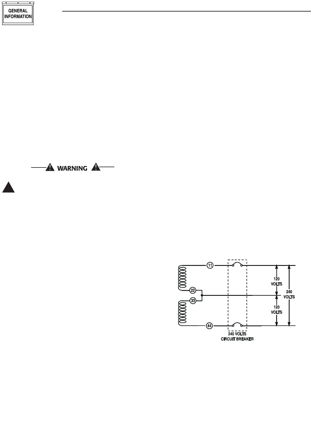
1.4 GENERATOR AC CONNECTION
SYSTEMS
The generator was shipped from the factory with its
stator AC output leads connected in a single-phase,
three-wire generator AC connection system (Figure
1.1). The stator assembly in this system consists of a
pair of stationary windings, with two leads brought
out of each winding. Each single winding can supply
120VAC, 60 Hertz. When the two windings are
connected in series, a 240VAC, 60 Hertz output
results. Typically the two “hot” leads in the circuit are
Wires No. 11 and 44. The “Neutral” leads are the
junction of Wires 22 and 33.
Figure 1.1 - Generator AC Connection System
NOTE:
Rated power of generator is subject to and limited
by such factors as ambient temperature, altitude,
engine condition, and other factors. Engine power
will decrease about 3% for each 1000 feet above
3000 feet and will decrease an additional 1.5% for
each 10°F above 77°F. Maximum output power of
the generator is limited by maximum engine
power.
!
Section 1 - General Information
Centurion Liquid-cooled 15 kW and 25 kW Generators