


Generac
®
Power Systems, Inc. 19
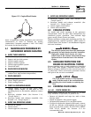
1. The base frame of the unit contains an optional
fuel inlet location that is capped at the factory.
Check that it is secured in place. The same
applies for any access ports in the roof of the
enclosure. If any of these caps are missing,
contact a Generac Authorized Dealer.
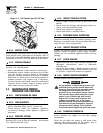
2. Inside the generator set, the chance of rodent
entry into the control panel is greatly reduced by
the inclusion of adjustable wire connectors.
Check that the wire connector screws are tight,
thus closing off any gap between the access holes
and the wires.
4.7 OUT OF SERVICE PROCEDURE
4.7.1 REMOVAL FROM SERVICE
If the generator cannot exercise every seven days, and
it is to be out of service longer than 90 days, prepare
the generator for storage as follows:
1. Start the engine and let it warm up.
2. Close the fuel shutoff valve in the fuel supply line
and allow the unit to shut down.
3. Once the unit has shut down, it will signal a fault
on the control panel.
4. Set the Auto/Off/Manual switch to OFF and turn
off the utility power to the transfer switch.
5. While the engine is still warm from running,
drain the oil completely. Refill the crankcase with
SAE 15W-40 oil having API Service Class SD, SE
or SF. (See “Engine Oil Recommendations” in
Section 1.14)
6. Attach a tag to the engine indicating the viscosity
and classification of the oil in the crankcase.
7. Remove the spark plug(s) and spray fogging agent
into the spark plug(s) threaded openings.
Reinstall and tighten the spark plug(s).
8. Remove the battery and store it in a cool, dry
room on a wooden board. Never store the battery
on any concrete or earthen floor.
9. Clean and wipe the entire generator.
4.7.2 RETURN TO SERVICE
To return the unit to service after storage, proceed
as follows:
1. Verify that utility power is turned off to the
transfer switch and that the Auto/Off/Manual
switch is set to OFF.
2. Check the tag on the engine for oil viscosity and
classification. Verify that the correct recom-
mended oil is used in engine. See Section 1.14. If
necessary, drain and refill with the proper oil.
3. Check the battery. Fill all cells to the proper level
with deionized water. DO NOT USE TAP WATER
IN THE BATTERY. Remove the battery before
charging. Recharge the battery to 100 percent
state of charge, or, if defective, replace the battery
with a 12-volt DC Group 26/26R battery rated for
75 amp hours 525 CCA minimum @ 0° F.
4. Clean and wipe the entire generator.
5. Reconnect the battery. Observe battery polarity.
Damage may occur if the battery is connected
incorrectly.
6. Open the fuel shutoff valve.
7. Start the unit by moving the Auto/Off/Manual
switch to MANUAL. Allow the unit to warm up
thoroughly.
8. Stop the unit and set the Auto/Off/Manual switch
to AUTO.
9. Turn on the utility power to the transfer switch.
10. The generator is now ready for service.
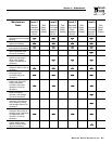
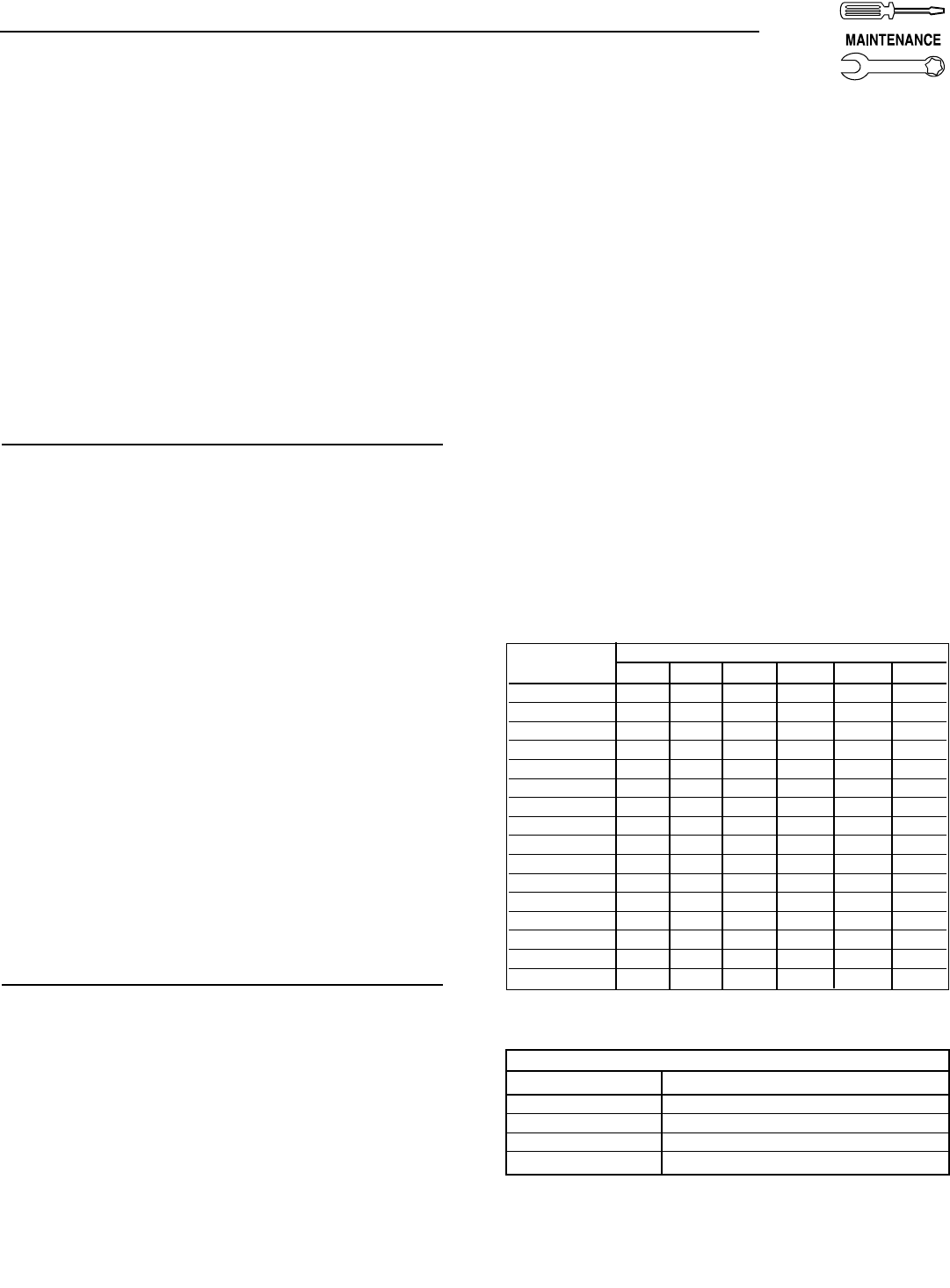
4.8 FUEL PIPE SIZING
Refer to chart for proper sizing of fuel supply piping.
Insufficient fuel pipe size can cause hard starting,
poor engine performance and inability to carry load.
NG and LP Vapor Pipe Sizing Chart:
* Consumption in Cubic Feet Per Hour.
Section 4 — Maintenance
Centurion Liquid-cooled 15 kW and 25 kW Generators
Length of Pipe Iron Pipe Size (IPS Inches)
in Feet ½" ¾" 1" 1 ¼" 1 ½" 2"
15 76 172 345 750 1,220 2,480
30 52 120 241 535 850 1,780
45 43 99 199 435 700 1,475
60 38 86 173 380 610 1,290
75 77 155 345 545 1,120
90 70 141 310 490 1,000
105 65 131 285 450 920
120 120 270 420 860
150 109 242 380 780
180 100 225 350 720
210 92 205 320 660
240 190 300 620
270 178 285 580
300 170 270 545
450 140 226 450
600 119 192 390
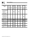
PERIODIC REPLACEMENT PARTS
Part Name Generac’s Part Number
Oil Filter # 0A45310244
Radiator Cap # 046627
Air Cleaner # 059402
Spark Plug # 0A45310275