


Generac
®
Power Systems, Inc. 9
NOTE:
For more information about the installation of a
standby system, you can order Engine-Generator
Standby Electric Power Systems Installer’s Guide
and Reference Manual (part #046622) from a
Generac Authorized Service Dealer.
2.1.1 NFPA STANDARDS
The following published standards booklets
pertaining to standby electric systems are available
form the National Fire Protection Association (NFPA),
Batterymarch Park, Quincy, MA 02269:
• NFPA No. 37, STATIONARY COMBUSTION
ENGINES AND GAS TURBINES.
• NFPA No. 76A, ESSENTIAL ELECTRICAL
SYSTEMS FOR HEALTH CARE FACILITIES.
• NFPA No. 220, STANDARD TYPES OF BUILDING
CONSTRUCTION
• NFPA No. 68, GUIDE FOR EXPLOSION VENTING
• NFPA No. 70, NATIONAL ELECTRICAL CODE.
• NFPA No. 30, FLAMMABLE AND COMBUSTIBLE
LIQUIDS CODE.
• NFPA No. 10, INSTALLATION, MAINTENANCE
AND USE OF PORTABLE FIRE EXTINGUISHERS.
2.1.2 OTHER PUBLISHED STANDARDS
In addition to NFPA standards, the following
information pertaining to the installation and use of
standby electric systems is available:
• Article X, NATIONAL BUILDING CODE, available
from the American Insurance Association, 85 John
Street, New York, N.Y. 10038.
• AGRICULTURAL WIRING HANDBOOK, obtainable
from the Food and Energy Council, 909 University
Avenue, Columbia, MO, 65201.
• ASAE EP-364.2, INSTALLATION AND
MAINTENANCE OF FARM STANDBY ELECTRIC
POWER, available from the American Society of
Agricultural Engineers, 2950 Niles Road, St.
Joseph, MI 49085.
• A52.1, AMERICAN NATIONAL STANDARD FOR
CHIMNEYS, FIREPLACES AND VENTING
SYSTEMS, available from the American National
Standard Institute, 1430 Broadway, New York, N.Y.
10018.
2.2 GENERATOR LOCATION
Install the generator set, in its protective enclosure
outdoors, where adequate cooling and ventilating air
is always is available. Consider these factors:
• Install the unit where air inlet and outlet openings
will not become obstructed by leaves, grass, snow,
etc. If prevailing winds will cause blowing or
drifting, consider a windbreak to protect the unit.
• Install the generator on high ground where water
levels will not rise and endanger it.
• Allow sufficient room on all sides of the generator
for maintenance and servicing. Allow three feet of
space on all sides. NOTE: LOCAL LAWS OR
CODES MAY REQUIRE DIFFERENT OFFSET
DISTANCES.
• Where strong prevailing winds blow from one
direction, face the generator air inlet openings into
the prevailing winds.
• Install the generator as close as possible to the
transfer switch. This reduces the length of wiring
and conduit.
• Install the generator as close as possible to the fuel
supply, to reduce the length of piping. HOWEVER,
REMEMBER THAT LAWS OR CODES MAY
REGULATE THE DISTANCE.
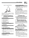
2.3 GENERATOR MOUNTING AND
SUPPORT
Retain the generator compartment to a steel mesh or
rebar reinforced concrete slab with 1/4-inch masonry
type anchor bolts. Be sure the bolts are long enough
to retain the compartment. The slab should be at
least five inches thick and should extend beyond the
enclosure to a distance of at least three inches on all
sides. See page 25 for generator major dimensions.
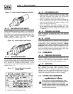
2.4 BASIC STANDBY ELECTRIC
SYSTEM
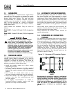
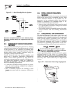
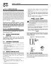
Figure 2.1 shows a schematic diagram of a basic
standby electric system. Both the UTILITY power
supply and the STANDBY (GENERATOR) output are
connected to an approved transfer switch. The
transfer switch is required by electrical code and
serves the following functions:
• Permits the LOAD circuits to be connected to only
one power supply at a time.
• Prevents electrical backfeed between the generator
and the UTILITY power circuits.
Notice that both the STANDBY and the UTILITY
power supplies to the transfer switch are protected
against overload by a main line circuit breaker.
Section 2 — Installation
Centurion Liquid-cooled 15 kW and 25 kW Generators