


Generac
®
Power Systems, Inc. 13
3.1 USING A STANDARD “GTS”
TRANSFER SWITCH
When required, the pre-packaged standby generator
can be installed with an engineered Generac “GTS”
type engineered automatic transfer switch.
When a GTS type transfer switch is used, it controls
automatic operation and automatic transfer as
follows:
• Solid state circuits in the transfer switch monitor
utility power source voltage.
• When utility source voltage drops below a pre-set
level, transfer switch action closes the circuit. The
engine then cranks and starts as controlled by the
pre-packaged generator’s Control Module circuit
board.
• After the engine starts and when the generator AC
output voltage and frequency have reached a
pre-set value, transfer switch circuits signal the
transfer switch main contacts to actuate to the
“Standby” power source side. Generator AC output
then powers load circuits.
• When the utility power source voltage is restored
above a pre-set level, transfer switch solid state
circuits signal the switch main contacts to move
back to their utility power source side.
• Following re-transfer back to the utility power
source side, transfer switch circuit board action
opens the circuit. Engine then shuts down.
NOTE:
If the generator is installed in conjunction with an
engineered GTS type engineered transfer switch,
refer to the applicable transfer switch manual for
exact operating parameters and timing sequences.
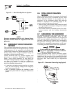
3.2 CONTROL CONSOLE
COMPONENTS
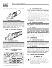
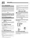
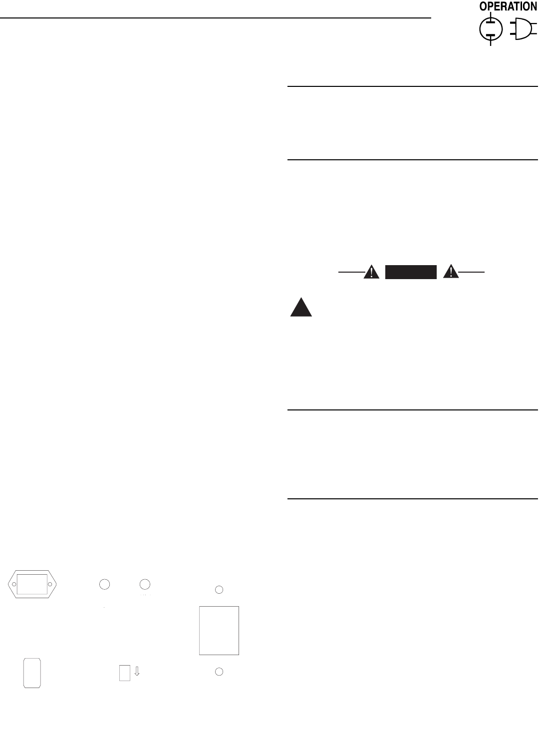
The components of a liquid-cooled generator control
console (Figure 3.1) are as follows:
Figure 3.1 - Liquid-Cooled Generator Panel
3.2.1 HOURMETER
Indicates time the generator has operated, in hours
and tenths of hours. Use the hourmeter along with
the periodic maintenance schedule for the generator
set.
3.2.2 AUTO/OFF/MANUAL SWITCH
Use this three-position switch as follows:
• Set the switch to AUTO for fully automatic
operation. See Section 3.4, “Automatic Operation”.
• Set switch to MANUAL position to crank and start
the generator engine.
• Set switch to OFF position to shut down an
operating engine. With OFF selected, operation will
not be possible.
With switch set to AUTO, engine can crank
and start suddenly without warning. Such
automatic start up normally occurs when
utility source voltage drops below a pre-set
level. To prevent possible injury that might be
caused by such sudden starts, set the
AUTO/OFF/MANUAL switch to OFF before
working on or around the unit. Then, place a
"DO NOT OPERATE" tag on control console.
3.2.3 FAULT INDICATOR LAMP
The lamp goes ON when one or more of the following
engine faults occurs and when engine shuts down.
• Low oil pressure • Overcrank
• High coolant temperature • Overspeed
• Low coolant level
3.2.4 15 AMP FUSE
The fuse protects the control console’s DC control
circuit against electrical overload. If the fuse has
melted open due to an overload, or is removed,
engine cranking and startup may still occur when the
AUTO/OFF/MANUAL switch is placed in the AUTO or
MANUAL positions.
NOTE:
To disable the control board and thus prevent
potential crank and run, the 15 amp fuse AND the
7.5 amp in-line fuse must both be removed or the
battery cables should be disconnected.
Should you need to replace the fuse, use only an
identical AGC 15-amp replacement fuse.
!
DANGER
AUTO
MANUAL
OFF
FUSE
15-A
AGC
FAULT
INDICATOR
SET
EXERCISE
TIME
ON
HOUR METER
Section 3 - Operation
Centurion Liquid-cooled 15 kW and 25 kW Generators