


Generac
®
Power Systems, Inc. 7
Section 2 – Operation
QUIETPACT™ 65D Recreational Vehicle Generator
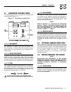
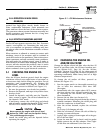
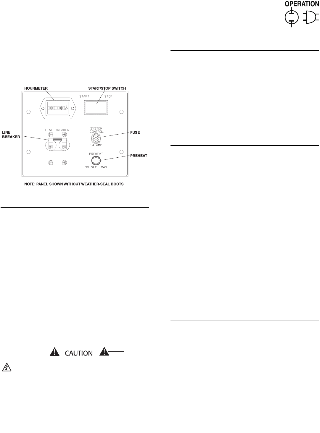
2.1 GENERATOR CONTROL PANEL
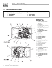
The following features are mounted on the generator
control panel (Figure 2.1):
Figure 2.1 – Generator Control Panel
2.1.1 HOURMETER
This indicates the length of time the engine/generator
has operated, in hours and tenths of hours. Use
the hourmeter to ensure that the periodic mainte-
nance tasks for your generator are completed on a
timely basis.
2.1.2 START/STOP SWITCH
To crank and start the engine, hold this switch in the
START position. Release the switch when the engine
starts. To stop an operating engine, press and hold
the switch in the STOP position until the engine shuts
off. The switch’s center position is the RUN position.
2.1.3 FUSE
The 14-amp fuse protects the engine’s DC control cir-
cuit against electrical overload. If the fuse element
has melted open due to overloading, the engine can-
not be cranked. If you must replace the fuse, use only
an identical replacement (i.e., SFE-14).
If a fuse element melts, you should find the
cause of the overload before replacing the fuse.
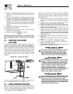
2.1.4 LINE BREAKER
The line (i.e., main) breaker protects the generator’s
AC output circuit against overload and provides a
method of turning OFF the generator’s 230-volt AC
output to the vehicle circuits. The QUIETPACT™ 65D
has two 30-amp breakers.
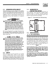
NOTE:
Refer to Section 1.4, “Generator AC Connection
System,” (Page 5). Individual installations will dif-
fer. If an overload occurs, the dual breakers will
open the ungrounded (i.e., hot) stator leads (11
and 44 in Figure 1.1, Page 5).
2.1.5 PREHEAT SWITCH
The diesel engine is equipped with glow plugs, one
for each cylinder. When you press the preheat switch,
the glow plugs heat the engine combustion chamber,
allowing for quicker starts when the engine is cold.
Pressing the preheat switch also operates the fuel
pump.
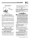
2.2 OPTIONAL REMOTE START/STOP
This generator is equipped with a plug-in connector
that can be interfaced with an optional remote panel
provided inside the vehicle. This option allows you to
start and stop the generator conveniently from with-
in the vehicle. Refer to Part II - Installation
Instructions, Section 2.8, for details on the remote
start/stop option.
2.3 BEFORE STARTING THE ENGINE
NOTE:
Instructions and information in this manual
assume the generator has been properly installed,
connected, serviced, tested and adjusted by a
qualified installation technician or installation
contractor.
2.3.1 INSTALLATION
Generator installation must have been properly com-
pleted so that it complies with all applicable codes,
standards, and regulations and with the manufactur-
er's recommendations.
◆
◆
◆
◆
◆
◆