


26 Generac
®
Power Systems, Inc.
2.3 COOLING AND VENTILATING AIR
It is absolutely essential that an adequate flow of air
for cooling, ventilation, and engine combustion be
supplied to the generator set. Without sufficient air-
flow, the engine/generator quickly overheats. Such
overheating can cause serious operating difficulties
and also may cause fire and personal injury. The
installer must make sure that sufficient air is avail-
able to the generator for cooling, ventilating, and
combustion. The installer also must provide a path
for exhausting the cooling air to the exterior of a com-
partment, if so equipped.
Never use discharged cooling air for heating or
permit such air to enter the vehicle interior. This
air contains deadly carbon monoxide gas and
other poisonous, flammable, or explosive gases.
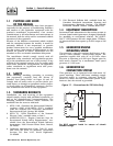
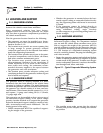
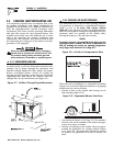
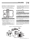
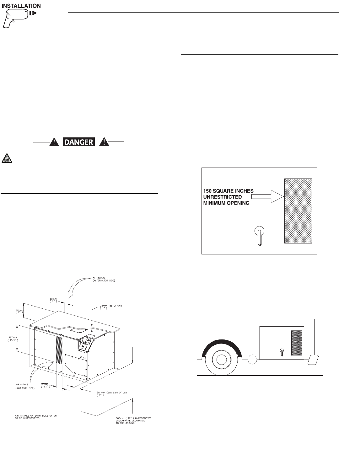
2.3.1 GENERATOR AIRFLOW
This unit uses an impellar fan located on the alterna-
tor drive pulley to cool the alternator’s internal com-
ponents. Air is drawn through the alternator and
expelled radially behind the drive pulley. An engine-
driven centrifugal blower draws in cooling air
through air inlet openings, moves that air around the
engine/generator and across the radiator, then dis-
charges that air out the bottom (see Figure 2.7).
Figure 2.7 – Airflow Through Engine/Generator
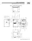
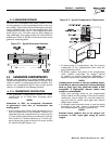
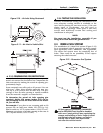
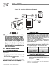
2.3.2 COOLING AIR INLET OPENINGS
The minimum size of the air inlet opening, whether
the generator is housed in a conventional compart-
ment or not, is at least 150 square inches
(975 cm
2
) (see Figure 2.8). This rule applies whether
inlet air is brought in through an opening in the com-
partment door, an opening in the vehicle skirt,
through ductwork, or by any other means.
NOTE:
Screening, louvers, or expanded metal that cover air
openings restrict airflow. You must compensate for
this by making the actual air opening proportion-
ately larger. See Section 2.3.3 (Page 27).
Figure 2.8 – Air Inlet in Compartment Door
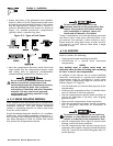
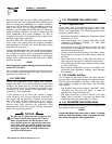
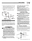
When the unit is installed on a suspended mounting
system, one of several different methods of supplying
airflow may be used as follows:
• Provide a door in the vehicle skirt having an air
inlet opening (Figure 2.9).
Figure 2.9 – Suspended Mount: Inlet Door
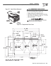
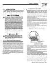
• Use ductwork (Figure 2.10, Page 27). The installer
must be sure air is available to the sides of the gen-
erator for proper air intake.
• Provide an opening in the vehicle skirt and space
around the generator for cooling airflow (Figure
2.11, Page 27). Recommended clearance around
all sides of the generator is at least 2 inches (50
mm).
◆
◆
Section 2 – Installation
QUIETPACT™ 65D Recreational Vehicle Generator