


3GDL 30A Installation Instructions
Connecting the GDL 30A to a Chartplotter
Connect the GDL 30A to a chartplotter by using the Garmin Marine Network Cable (included). See the installation instructions for your
chartplotter for more detailed information on setting up a Garmin Marine Network.
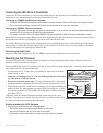
Connecting to a GPSMAP 4000/5000 series chartplotter:
A GPSMAP 4000/5000 series chartplotter has three network connectors available. Connect the GDL 30A to any of these connectors.
If you have multiple chartplotters, connect the GDL 30A to an open connector on any one of the chartplotters.
Connecting to a GPSMAP 3000 series chartplotter:
A GPSMAP 3000 series chartplotter has one network connector available. If you do not have any other Garmin Marine Network devices,
connect the GDL 30A directly to the GPSMAP 3000 series chartplotter.
If you need to connect the GDL 30A to multiple GPSMAP 3000 series chartplotters, a GMS 10 Network Port Expander is required.
Garmin does not recommend cutting the Marine Network cable, though cutting the cable may be necessary in certain circumstances. Refer to
the installation instructions for your chartplotter if you need to cut the Marine Network cable.
If you need to drill a hole in your boat, use the included grommet that is specically designed to cover holes drilled for the Garmin Marine
Network Cable. If a longer cable is needed, contact Garmin or your Garmin dealer. To ensure safety, use tie-wraps, fasteners, and sealant to
secure the cable along a route and through any bulkhead or deck.
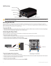
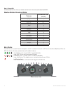
Connecting the Audio Cable
Connect the audio cable (included) to the GDL 30A AUDIO connector and to the audio inputs on your stereo receiver.
Mounting the GA 32 Antenna
You can surface mount the GA 32 antenna, attach it to a standard 1 in. OD pipe-threaded-pole marine mount (14 threads-per-inch—not
included), or install the antenna under berglass.
Select a suitable location for the GA 32 antenna on your boat. To ensure the best reception, mount the GA 32 antenna in a location that has a
clear, unobstructed view of the sky in all directions.
Avoid mounting the GA 32 antenna where it is shaded by the superstructure of the boat, a
radome antenna, or mast.
. The length of the antenna cable is set to provide
optimal performance. Shortening the cable adversely effects the performance of the GA 32.
If additional antenna cable is needed, Garmin recommends a 50-foot cable from Delphi, part
number SA10006. The following adapters are required: BNC plug to SMB jack – available
from Newark, part number 92C7329 and BNC jack to SMB plug – available from Newark,
part number 92C7330.
Temporarily secure the antenna in the preferred mounting location and test it for correct
operation. If you experience interference from other electronics, try a different location. When
you verify correct operation, permanently mount the antenna.
Surface mounting the GA 32 Antenna
1. Use the surface-mount bracket as your mounting template.
Use a center punch to mark the three screw locations on the surface.
Use a pencil to trace the cable hole in the center of the bracket.
Set the surface-mount bracket aside. Do not drill through the surface-mount bracket.
•
•
•
•
•
•
•
•
•
•
•
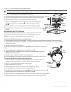
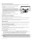
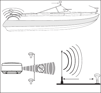
GA 32 Antenna Placement Considerations
SS BARNETT
Radar
VHF Radio Antenna
3 ft.
(1 m)
EMI (Electromagnetic Interference)
from engine components
Best
Better
Good
EMI
Above - best
Below - OK
3 ft. (1 m)
3 ft. (1 m)
GA 32 Antenna Placement Considerations
SS BARNETT
Radar
VHF Radio Antenna
3 ft.
(1 m)
EMI (Electromagnetic Interference)
from engine components
Best
Better
Good
EMI
Above - best
Below - OK
3 ft. (1 m)
3 ft. (1 m)