


A-9
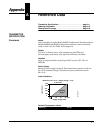
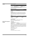
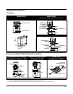
DIMENSIONAL DRAWINGS
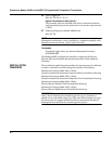
Transmitter
Enclosure and Model 244EC Configuration Interface
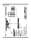
Model 244ER Model 244EH
Shown with Standard Compression Screw Terminals
Shown with WAGO
®
Spring Clamp Terminals
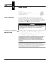
Dimensions are in millimeters (inches)
36
(1.4)
104
(4.1)
82
(3.2)
Sensor Terminals
Power Terminals
644-1105E01A. 1101A01A
644-1360B02A
33 (1.30)
WAGO
®
Spring
Clamp Sensor
Terminals
24 (1.0)
Power Terminals
Communication
Terminals
Failure Mode Switch
33 (1.3)
60 (2.4)
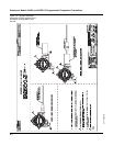
Standard Sensor
Terminals
Communication
Terminals
644-1360A02A
Failure Mode
Switch
34 (1.33)
60 (2.4)
33 (1.3)
Power
Terminals
24 (1.0)
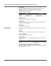
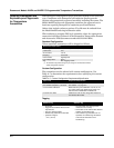
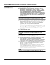
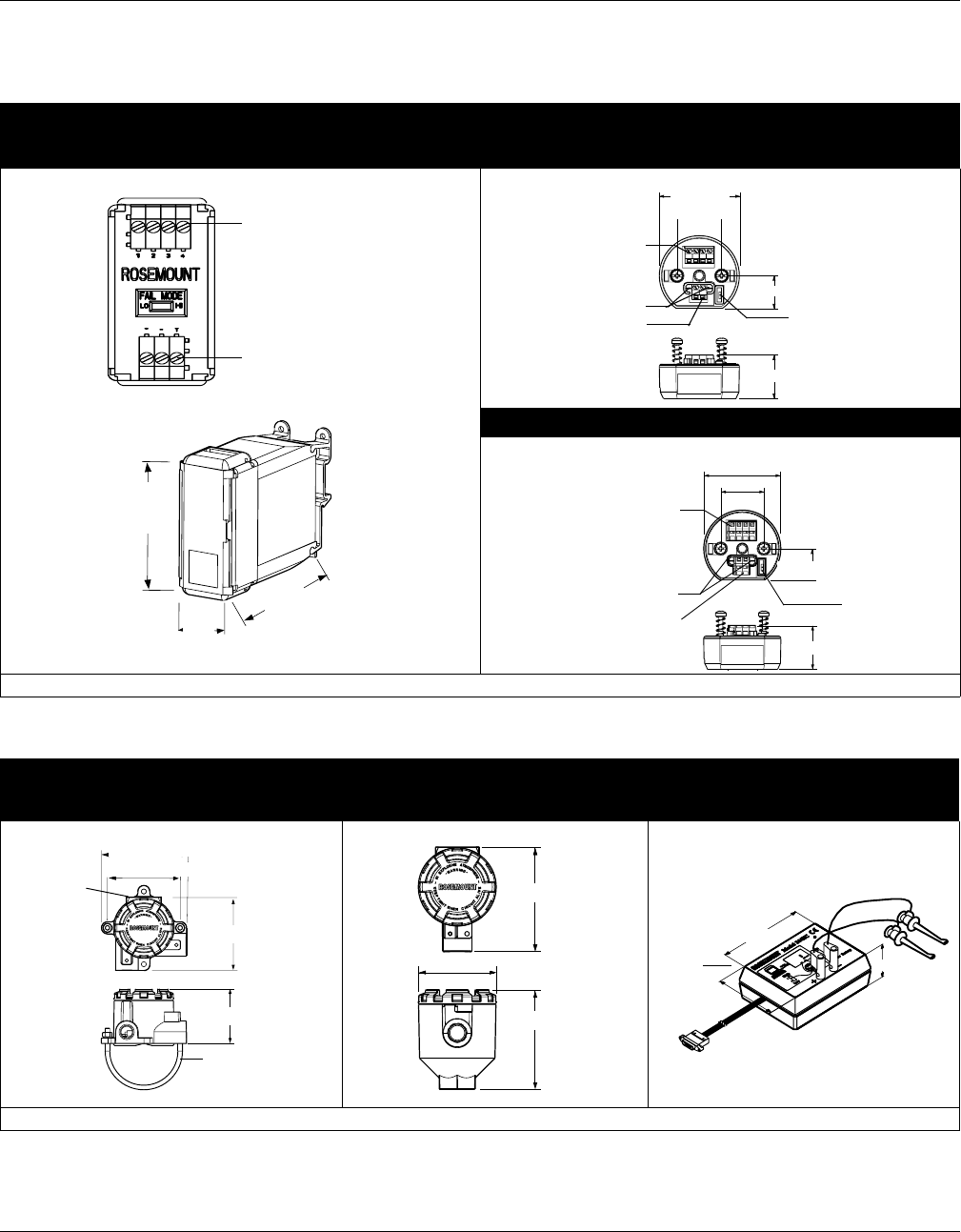
Threaded-Sensor Universal
Head (option code J5 or J6)
(1)
Integral DIN Style Sensor
Connection Head
(2)
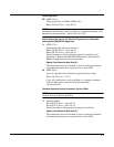
Model 244EC
Configuration Interface
Dimensions are in millimeters (inches)
(1) A “U” Bolt is shipped with each universal head unless assembly option code X1, X2, or X3 is ordered.
However, since the head can be integrally mounted to the sensor, it may not need to be used.
(2) Note: The DIN Style Integral sensor connection head is only available through Volume 2 of the sensors product data sheet.
95 (3.74)
96 (3.76)
112 (4.41)
SST “U” Bolt
Mounting,
2-inch Pipe
Label
75 (2.93)
1
04 (4.09)
100 (3.93)
7
8
(
3.06
)
0.61 m (2 ft)
Configuration Leads
38 (1.5)
1.83 m (6 ft) Ribbon Cable
84 (3.3)
114 (4.5)
644-4420A02A, 4410AO1A, 3300A01A