


2-5
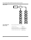
INSTALLATION
PROCEDURES
Transmitter Refer to the appropriate procedure and the accompanying illustrations
when installing the transmitter.
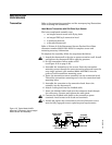
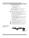
Head Mount Transmitter with DIN Plate Style Sensor
The least complicated assembly uses:
• an integral mount sensor with flying leads
• an integral DIN style connection head
•a standard extension
•a threaded thermowell
Refer to Volume 2 of the Rosemount Sensors Product Data Sheet
(document number 00813-0101-2654) for complete sensor and
mounting accessory information.
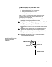
To complete the assembly, follow the steps described below.
1. Attach the thermowell to the pipe or process container wall. Install
and tighten the thermowell before applying pressure.
2. Set the transmitter failure mode switch
(see Figure 2-13 on page 2-16).
3. Assemble the transmitter to the sensor. Push the transmitter
mounting screws through the sensor mounting plate and insert the
snap rings (optional, part number 00644-4432-0001) into the
groove of each transmitter mounting screw.
4. Insert the transmitter-sensor assembly into the connection head.
Thread the transmitter mounting screw into the connection head
mounting holes.
5. Assemble the extension to the connection head. Insert the
assembly into the thermowell.
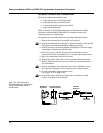
6. Attach a cable gland into the shielded cable.
7. Insert the shielded cable leads into the connection head through
the cable entry. Connect and tighten the cable gland.
8. Connect the shielded cable leads to the transmitter power
terminals. Avoid contact with leads and terminals.
9. Install and tighten the connection head cover. Enclosure covers
must be fully engaged to meet explosion-proof requirements.
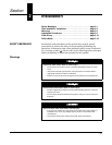
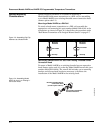
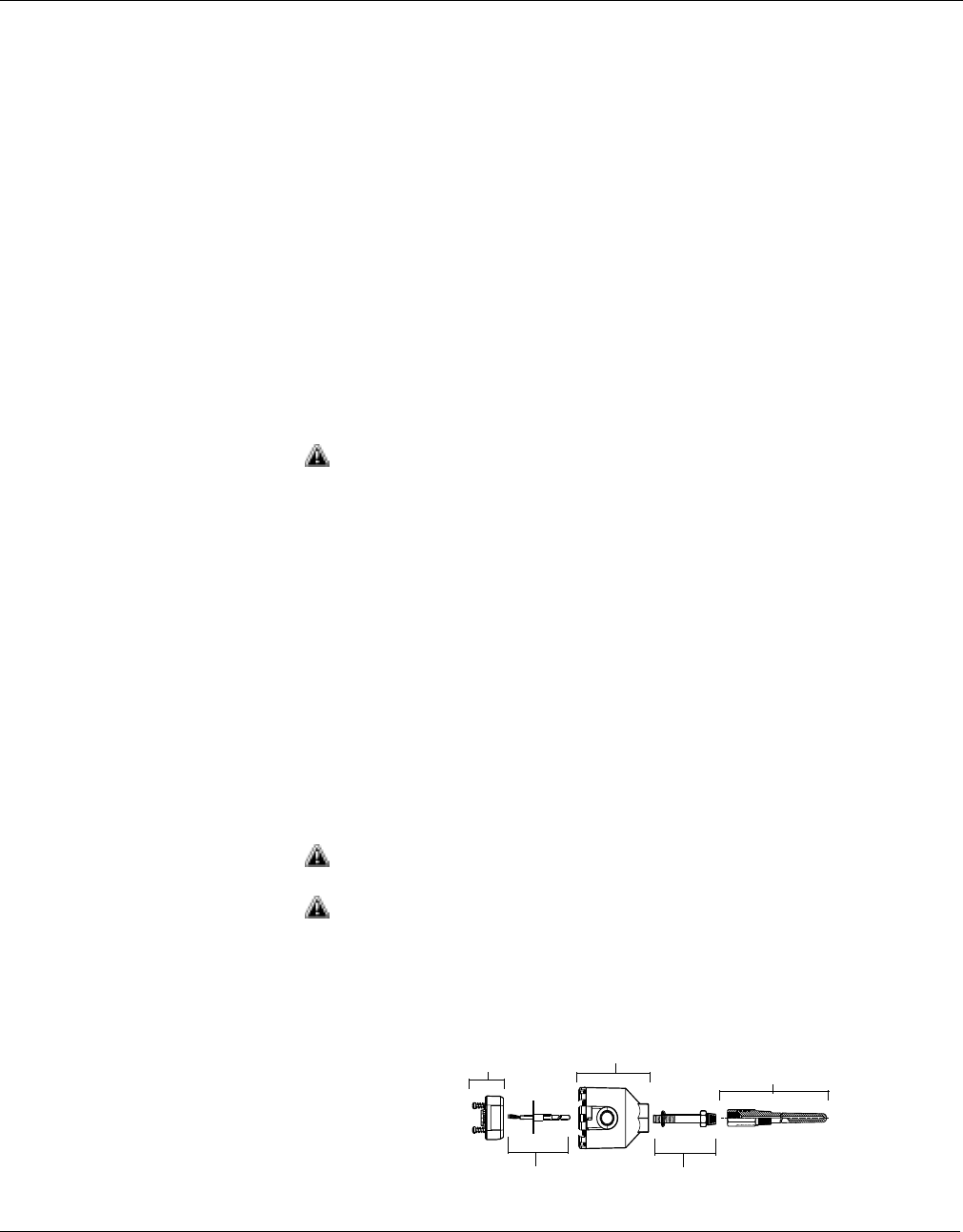
Figure 2-5. Typical Model 244EH
Mounting Configuration Using Integral
Mount Sensor and Assembly
644-0000B04A
Model 244EH
Transmitter
Integral Mount Sensor
with Flying Leads
Threaded Extension
Threaded
Thermowell
C
onnection
Head