


2-7
Rail Mount Transmitter with Integral Mount Sensor
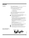
The least complicated assembly uses:
• an integral mount sensor with terminal block
• an integral DIN style connection head
•a standard extension
•a threaded thermowell
Refer to Volume 2 of the Rosemount Sensors Product Data Sheet
(document number 00813-0101-2654) for complete sensor and
mounting accessory information.
To complete the assembly, follow the procedure described below.
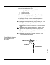
1. Attach the transmitter to a suitable rail or panel.
2. Attach the thermowell to the pipe or process container wall. Install
and tighten the thermowell before applying pressure.
3. Attach the sensor to the connection head and mount the entire
assembly to the thermowell.
4. Attach sufficient lengths of sensor lead wire to the sensor terminal
block.
5. Attach and tighten the connection head cover. Enclosure covers
must be fully engaged to meet explosion-proof requirements.
6. Run sensor lead wires from the sensor assembly to the transmitter.
7. Set the transmitter failure mode switch
(see Figure 2-13 on page 2-16).
8. Attach the sensor and power leads to the transmitter. Avoid
contact with leads and terminals.
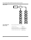
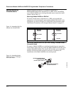
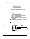
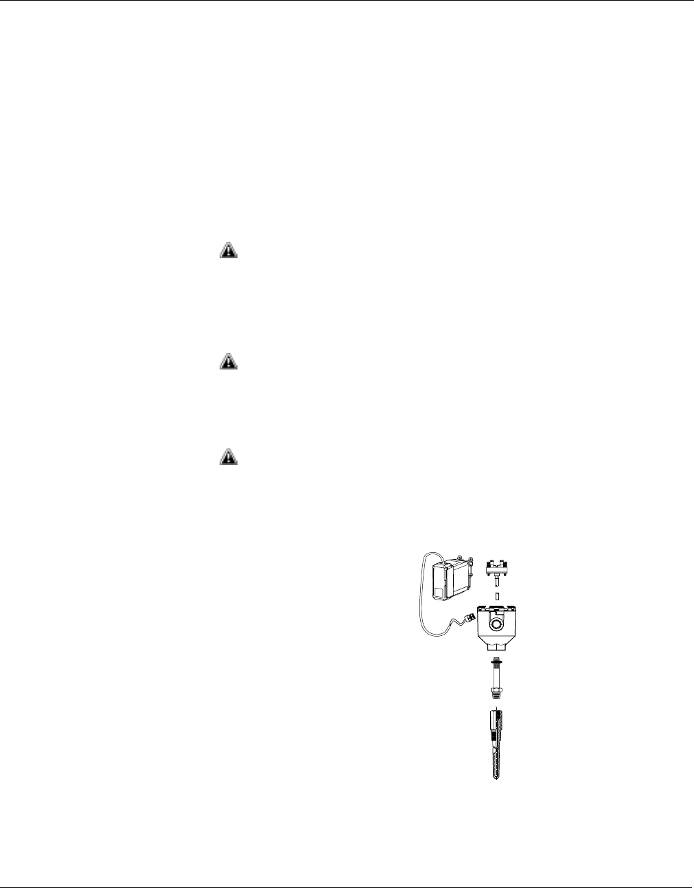
Figure 2-7. Typical Rail Mount
Transmitter Mounting Configuration
Using Integral Mount Sensor
and Assembly
Integral Mount Sensor
with Terminal Block
Connection Head
Standard Extension
Threaded Thermowell
Rail Mount Transmitter
Sensor Leads
with Cable Gland
644-0000C04A