


2-15
•Pt100 2-wire RTD:
Lead wire resistance seen by the transmitter = 150 m × 2 wires ×
0.025
Ω/m = 7.5 Ω
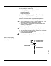
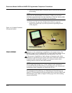
Thermocouple or Millivolt Inputs
For integral mounting applications, the thermocouple can be
connected directly to the transmitter. If mounting the transmitter
remotely from the sensor, use appropriate thermocouple extension
wire. Make connections for millivolt inputs with copper wire. Use
shielding for long runs of wire.
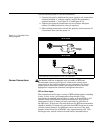
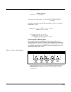
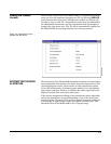
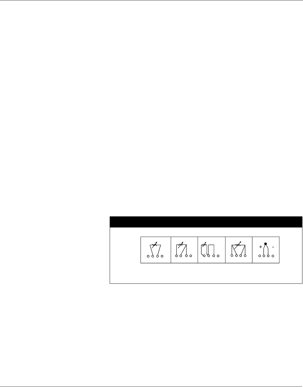
Figure 2-12. Sensor Wiring Diagrams
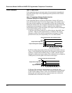
Basic Error
Lead Wire Resistance
α
Pt
R
o
×()
----------------------------------------------------------=
Error due to amb. temp. variation
α
Cu
()∆T
amb
()× Lead Wire Resistance()×
α
Pt
()R
o
()×
-----------------------------------------------------------------------------------------------------------------=
Basic error
7.5 Ω
0.00385 Ω / Ω°C()100 Ω()×
--------------------------------------------------------------------------------- 19.5 °C==
Error due to amb. temp. var. of 25 °C±
0.0039 Ω / Ω°C()25 °C()× 7.5 Ω()×
0.00385 Ω / Ω°C()100 Ω()×
-------------------------------------------------------------------------------------------------------
1.9 °C±==
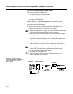
Model 244E Sensor Connections
* Rosemount Inc. provides 4-wire sensors for all single element RTDs. You can use these
RTDs in 3-wire configurations by leaving the unneeded leads disconnected and insulated
with electrical tape.
** The transmitters must be configured for a 3-wire RTD in order to recognize an RTD with a
compensation loop.
12341234 1234 12
3
41234
644-0000B01A
1
2-wire
RTD
and ⍀
3-wire
RTD
and ⍀
4-wire
RTD
and ⍀
T/C
and mV
RTD with
Comp.
Loop
*
**