


35
Troubleshooting, Adjustment & Repair
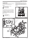
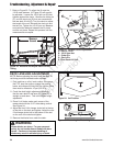
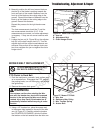
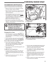
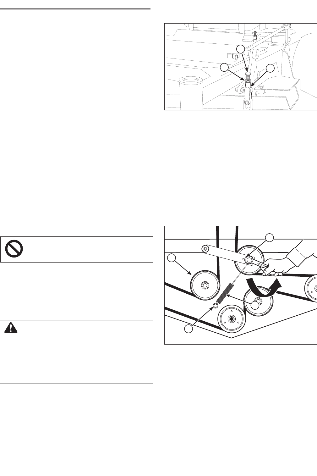
Figure 26. Deck Level Adjustment
A. Jam nut
B. Adjustment Bolt
C. Chain Hanger Clevis
A
B
C
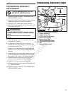
6. Manually position the left hand mower blade so
that the tip of the blade is pointing towards the
front and back of the mower. Measure from the
front tip of the blade on the cutting edge to the
ground. Record this distance. Measure from the
back tip of the blade on the cutting edge to the
ground. Record this distance.
Repeat this process for the right hand mower
blade.
The front measurement should be 3” and the
rear measurement should be 3-1/4”. If the
measurements are correct, no further adjustment
is necesary. If they are not correct continue with
Step 7.
7. Loosen the jam nut (A, Figure 26) on the adjuster
bolt (B) in the chain hanger clevis (C). Turn the
adjuster bolt until the correct measurements are
achieved. Ensure that all four hanger chains are
taut, then retighten the jam nut against the chain
hanger clevis.
MOWER BELT REPLACEMENT
PTO Clutch to Deck Belt
1. Park the machine on a smooth, level surface such
as a concrete floor. Disengage the PTO, engage
the parking brake, turn off the engine, and remove
the ignition key.
2. Remove the mower deck guard.
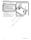
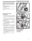
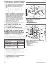
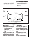
3. Using a 1/2” breaker bar, place the square end
in the square hole located on the end of the idler
arm (A, Figure 27). Carefully rotate the breaker
bar COUNTER-CLOCKWISE, which will relieve
the tension on the belt exerted from the idler arm.
To avoid damaging belts, DO NOT
PRY BELTS OVER PULLEYS.
WARNING
Use extreme caution when rotating the idler
arm with the breaker bar, due to the increased
tension in the spring as the idler arm is being
rotated. Injury may result if the breaker bar is
prematurely released while the spring is under
tension.
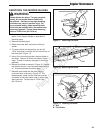
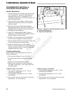
Figure 27. Mower PTO Belt
A. Idler Arm
B. Stationary Idler Pulley
C. Idler Tension Spring
D. Anchor Bolt
B
A
C
C
Not for
Reproduction