


42
www.ferrisindustries.com
Troubleshooting, Adjustment & Repair
REAR TIRE CAMBER ADJUSTMENT
The rubber bushings in the cast A-arms may stretch
and wear with time and adversely affect the angle
that the rear tire runs against the ground.
To evaluate if the rear tire camber should be
adjusted, park the machine on a flat and level surface
and view the machine from behind. If you can visually
notice that the top of either rear tire is angled towards
the machine then the rear tire camber needs to be
adjusted.
To adjust the camber you will need to order and
install the correct amount of camber shims (P/N
5100332) for each tire that needs to be adjusted from
your dealer. Shims should only be installed in even
numbered quantities
To discover how many shims are needed:
1. Park the machine on a flat level surface.
Disengage the PTO, stop the engine, remove the
ignition key, and engage the parking brake.
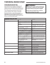
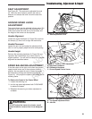
2. Place a carpenters square against the rear tire.
The bulge in the sidewall will not allow the square
to contact the bottom outside edge of the tire
where it first contacts the ground.
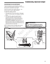
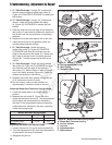
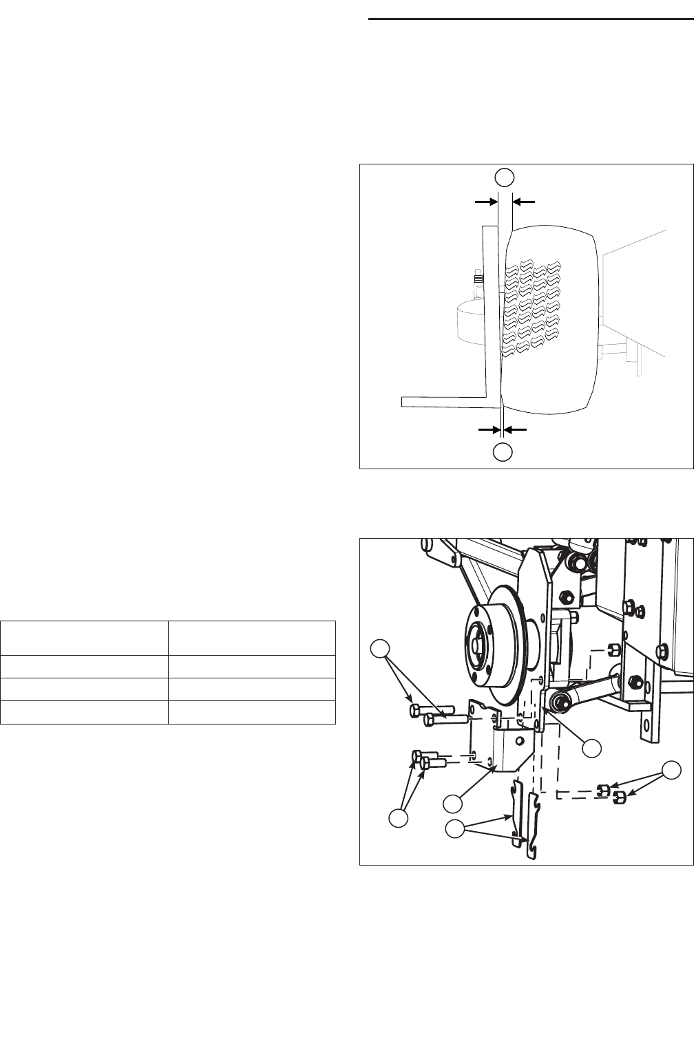
3. See Figure 36. Measure and record the distance
from the carpenters square to the top of the tire
(A, Figure 36). Measure and record the distance
from the carpenters square to the bottom of the
tire (B.) Subtract the bottom measurement from
the top measurement and reference the chart
below for the number of shims that are needed.
If the measurement is greater than .75” (1,91 cm)
contact your dealer.
Installing the camber shims:
1. Park the machine on a flat level surface.
Disengage the PTO, stop the engine, remove the
ignition key, and engage the parking brake.
2. Jack up the rear of the machine and secure with
jack stands. Remove the rear tire.
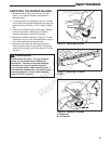
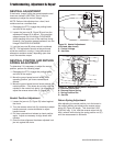
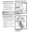
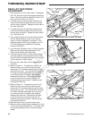
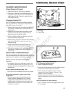
3. Loosen but do not remove the two (2) 1/2-20 X
3” (A, Figure 37) bolts and the (2) 1/2-20 X 1-3/4”
bolts (B.)
4. Install the new camber shims (E) between the
adjustable A-arm mount (C) and the rigid A-arm
mount (D.) The bottom of the slots on the camber
shim should rest snugly against the shaft of the
1/2-20 X 3” bolts and the 1/2-20 X 1-3/4” bolts.
Figure 37. Installing the Rear Tire Camber
A. 1/2-20 x 3” Bolt
B. 1/2-20 x 1-3/4” Bolt
C. Adjustable A-arm Mount
D. Rigid A-arm Mount
E. Camber Shims
F. 1/2-20 Hex Nylon Nut
F
B
C
D
E
A
B
A
Figure 36. Measuring the Camber Distance
A. Top Measurement
B. Bottom Measurement
5. Retighten the two (2) 1/2-20 X 3” bolts and the (2)
1/2-20 X 1-3/4” bolts.
6. Reinstall the tire.
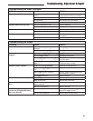
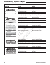
Distance Measured
Number of Shims
Needed
.2” (,51 cm) 2
.4” (1,04 cm) 4
.6” (1,52 cm) 6
Not for
Reproduction