


- 26 -
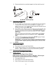
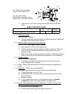
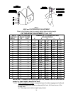
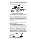
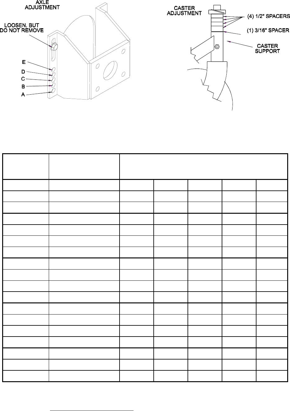
FIG. 8
AXLE and CASTER HEIGHT ADJUSTMENT
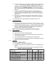
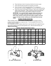
Refer to the following chart to properly adjust desired cutting height.
CUTTING HEIGHT ADJUSTMENT (1" to 4 1/4")
AXLE
POSITION
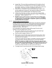
(FIG. 9)
NO. OF SPACERS
BELOW
CASTER
1/2" 3/16"
NUMBER OF 1/4” BLADE SPACERS
BELOW
SPINDLE
4 3 2 1 0
A 0 0 1" 1 1/4" 1 1/2" 1 3/4" 2"
A 0 1 1 1/8" 1 3/8" 1 5/8" 1 7/8" 2 1/8"
A 1 0 1 3/8" 1 5/8" 1 7/8" 2 1/8" 2 3/8"
B 0 1 1 3/8" 1 5/8" 1 7/8" 2 1/8" 2 3/8"
B 1 0 1 5/8" 1 7/8" 2 1/8" 2 3/8" 2 5/8"
B 1 1 1 3/4" 2" 2 1/4" 2 1/2" 2 3/4"
B 2 0 2" 2 1/4" 2 1/2" 2 3/4" 3"
C 1 1 1 7/8" 2 1/8" 2 3/8" 2 5/8" 2 7/8"
C 2 0 2 1/8" 2 3/8" 2 5/8" 2 7/8" 3 1/8"
C 2 1 2 1/4" 2 1/2" 2 3/4" 3" 3 1/4"
C 3 0 2 1/2" 2 3/4" 3" 3 1/4" 3 1/2"
D 2 1 2 3/8" 2 5/8" 2 7/8" 3 1/8" 3 3/8"
D 3 0 2 1/2" 2 3/4" 3" 3 1/4" 3 1/2"
D 3 1 2 3/4" 3" 3 1/4" 3 1/2" 3 3/4"
D 4 0 3" 3 1/4" 3 1/2" 3 3/4" 4"
E 3 1 2 7/8" 3 1/8" 3 3/8" 3 5/8" 3 7/8"
E 4 0 3 1/8" 3 3/8" 3 5/8" 3 7/8" 4 1/8"
E 4 1 3 1/4" 3 1/2" 3 3/4" 4" 4 1/4"
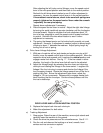
IMPORTANT: To achieve the highest quality of cut, blades should be level with the
ground, or tipped slightly down at the front.
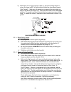
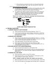
5.2.3 Blade engagement Linkage: Located between the blade engagement bellcrank
and blade engagement assist arm beneath the front, left hand corner of the
engine deck.
a) Stop engine and remove spark plug wire(s).