


- 10 -
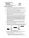
b) Loosen clamp on engine control plate (See Figure 2). Attach inner wire of
the throttle cable to the control plate lever and position cable under cable
clamp,
do not
tighten clamp.
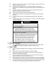
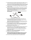
FIG 2
15 HP KAWASAKI SPEED CONTROL
(THROTTLE CABLE HOOK-UP)
c) Pull the cable to the right when facing the control plate until the alignment
holes in control plate lever and control plate line up. A 15/64” (6 mm) drill bit
can be inserted through these two holes to align them. Once the holes are
aligned, tighten clamp onto throttle cable.
d) Be sure the
choke adjusting screw just contacts the choke lever
when the
throttle control is in the full throttle position. Choke link should not move when
throttle control is moved to the full throttle position. Choke must be completely
closed when throttle lever is moved to the full forward “CHOKE” position.
NOTE: For 15 HP Kawasaki engines
:
There is not a “STOP” position.
The engine will continue to run when the throttle control is moved past the
rear detent. Turn the ignition switch to the “off” position to stop the engine.
e) Secure fuel line to throttle control cable with a small wire tie from the bolt
bag approximately 2” ahead of filter to keep fuel line away from hydraulic
lines to prevent vapor lock.
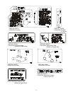
3.11 Install the blade engagement linkage to the bell crank on the
front
,
left hand
side of the engine deck. Insert rod through the hole from the outside and fasten
with hairpin cotter from bolt bag.
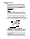
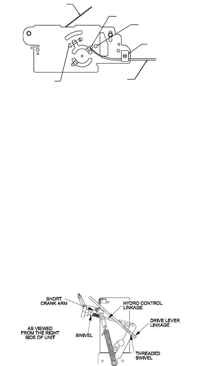
3.12 Note the square swivel at the end of the hydro control arm linkage. Place the
stud end of the swivel into the hole on the end of the short crank arm located at
the end of the speed control crank (top, rear of fuel tank support).
Install a 5/16” SAE washer and fasten with a 3/32” x 1/2” cotter pin from bolt bag.
Repeat on opposite side of unit (See Figure 3).
FIG. 3
HYDRO CONTROL LINKAGE SWIVEL & DRIVE LINKAGE SWIVEL
Control Alignment Holes
Control Plate Lever
Choke Link
Clamp
Control Cable
Choke Adjusting Screw